Wind turbine blade having a bond line adjacent a sandwich panel of the blade

a technology of bond line and blade, which is applied in the manufacture of final products, machines/engines, other domestic articles, etc., can solve the problems of reducing the possibility of crack initiation in the adhesive joints of the bond line between the blade shell and the blade structure, and reducing the strength of the blade structure. , to achieve the effect of reducing the amount of core material used, saving core material, and costing less to manufactur

Active Publication Date: 2017-08-22
LM WP PATENT HLDG
View PDF9 Cites 3 Cited by
  • Summary
  • Abstract
  • Description
  • Claims
  • Application Information

AI Technical Summary

Benefits of technology

[0010]By arranging the structural bond line adjacent the sandwich panel of the blade, the buckling strength of the blade structure is increased, as the forces experienced by the bond line are directly transferred into the relatively stiff sandwich panel, which reduces the possibility of crack initiation in the adhesive joints of the bond line between the blade shells. Furthermore, as the adhesive is provided directly adjacent the sandwich panel, the effectiveness of the bond between the shells is increased, which means that less adhesive is required in the blade construction. Preferably, no structural adhesive is provided at the leading and / or trailing edges of the blade, as the structural bond lines between the blade shells are moved to more effective locations, adjacent to or between sandwich panel constructions.
[0016]By positioning the structural bond line for the blade trailing edge adjacent a sandwich panel of the blade, the bending forces are more easily absorbed into the at least one sandwich structure of the blade shell. As a result, the trailing edge sandwich panel of the wind turbine blade has a stiffer edge support in the trailing edge region. This can result in savings in the core material used, as thinner sandwich panels are required to provide the same buckling stability, providing for wind turbine blades which are lighter and cost less to manufacture. Testing has shown that a 25% reduction in the amount of core material used is possible with the above configuration.
[0017]Furthermore, by moving the structural bond line away from the blade trailing edge, a reduction in the amount of adhesive used is possible, as additional adhesive is not wasted in the region of the trailing edge where the structural effectiveness of the bond line is comparatively worse.
[0019]By providing the structural bonds line between both the pressure- and suction-side sandwich constructions, the bending forces at the trailing edge of the blade are readily distributed into the structural elements of both the pressure- and suction-side shells.
[0021]By providing the structural bond line in an area having parallel bonding surfaces, the structural bond between the blade shells is of a better quality than a comparable bond between non-parallel bonding surfaces. Testing has shown that the Energy Release Rate (ERR) of a bond line arranged between parallel surfaces is 20% less than the ERR for a similar bond between non-parallel surfaces at the trailing edge of a blade. Such a reduction in ERR results in a bond having a reduced possibility of failure or cracking at the bond interface.

Problems solved by technology

By arranging the structural bond line adjacent the sandwich panel of the blade, the buckling strength of the blade structure is increased, as the forces experienced by the bond line are directly transferred into the relatively stiff sandwich panel, which reduces the possibility of crack initiation in the adhesive joints of the bond line between the blade shells.

Method used


Image

  • Wind turbine blade having a bond line adjacent a sandwich panel of the blade
  • Wind turbine blade having a bond line adjacent a sandwich panel of the blade
  • Wind turbine blade having a bond line adjacent a sandwich panel of the blade

Examples


Embodiment Construction

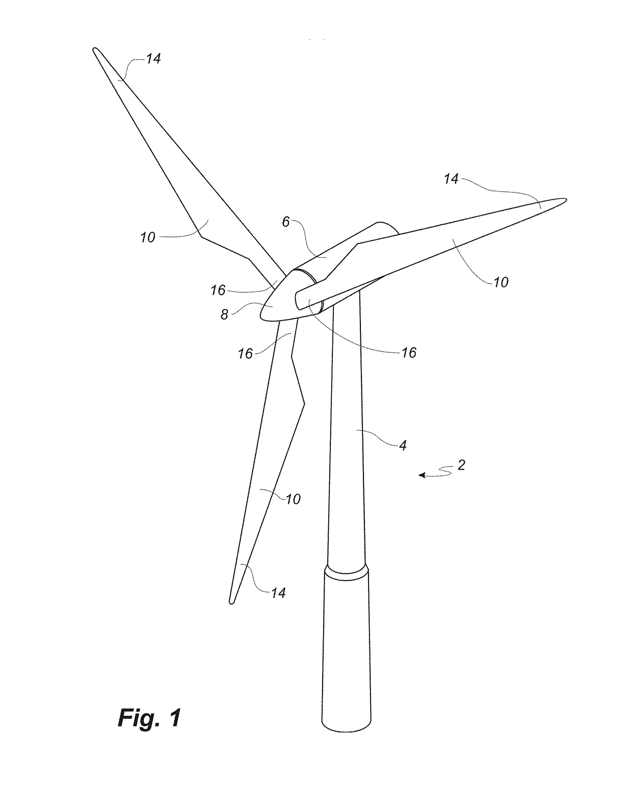
[0037]Embodiments of the invention will now be described, by way of example only, with reference to the accompanying drawings, in which:

[0038]FIG. 1 shows a wind turbine;

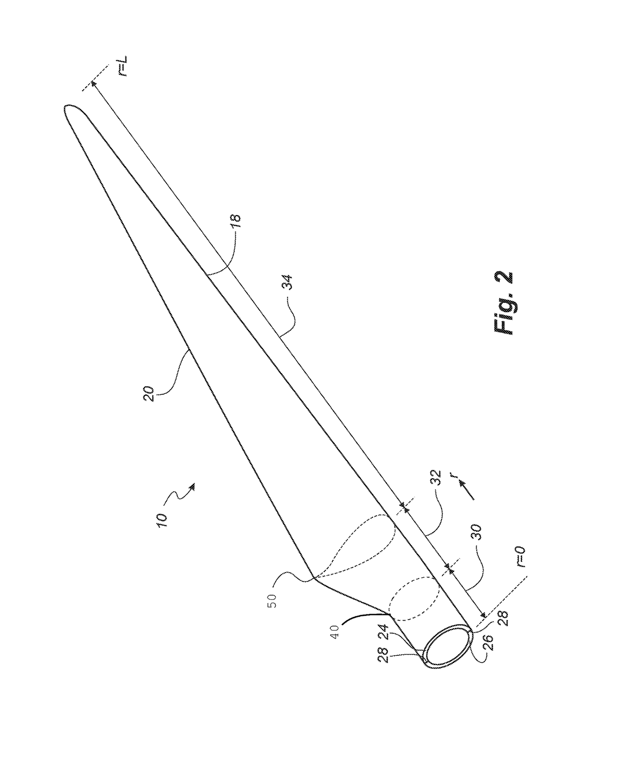
[0039]FIG. 2 shows a schematic view of a wind turbine blade according to the invention;

[0040]FIG. 3 shows a schematic view of an airfoil profile of the blade of FIG. 2;

[0041]FIG. 4 shows a schematic view of the wind turbine blade of FIG. 2, seen from above and from the side;

[0042]FIG. 5 illustrates a cross-sectional view of a wind turbine blade having a sandwich panel construction;

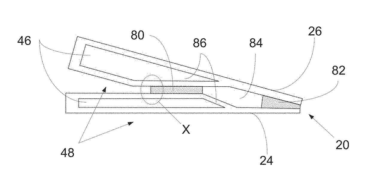
[0043]FIG. 6 illustrates an enlarged view of a prior art trailing edge structural bond of a wind turbine blade; and

[0044]FIG. 7 illustrates an enlarged view of a trailing edge structural bond of a wind turbine blade according to the invention.

[0045]It will be understood that elements common to the different embodiments of the invention have been provided with the same reference numerals in the drawings.

[0046]FIG. 1 illustrates a convention...


PUM

PropertyMeasurementUnit
lengthaaaaaaaaaa
lengthaaaaaaaaaa
thicknessaaaaaaaaaa

Abstract

A wind turbine blade and an associated method of manufacture is described, wherein a structural bond line of the blade is positioned to be adjacent to a sandwich panel construction of the blade. By locating the structural bond line nest to a sandwich region of the blade, the buckling strength of the joint is improved and the risk of crack initiation in the adhesive joint is reduced considerably. This allows for a reduction in the amount of structural adhesive used in the blade, and / or a reduction in the amount of core material which is required in the sandwich panel to maintain the required blade stiffness. A particular advantage is provided in the region of the trailing edge of the blade, wherein the relocated structural joint considerably reduces the risk of buckling in the trailing edge side of the blade.

Description

[0001]This is a National Phase Application filed under 35 U.S.C. 371 as a national stage of PCT / EP2014 / 065851, filed Jul. 23, 2014, an application claiming the benefit of European Application No. 13178448.0, filed Jul. 30, 2013, the content of each of which is hereby incorporated by reference in its entirety.FIELD OF THE INVENTION[0002]The present invention relates to a wind turbine blade, in particular a wind turbine blade having a structural bond line arranged adjacent a sandwich panel of the blade.BACKGROUND OF THE INVENTION[0003]Wind turbine blades are generally constructed by the formation of first and second blade shells by the layup and subsequent infusion with resin of fibre material, e.g. glass fibre and / or carbon fibre, in a suitably shaped mould. The blade shells, which are usually shaped to form complimentary pressure- and suction-side profiles of a wind turbine blade, can then be joined together along the leading and trailing edges of the shells to form a wind turbine b...

Claims


Application Information

Patent Timeline
Patent Type & Authority Patents(United States)
IPC IPC(8): F03D1/06B29L31/08
CPCF03D1/0675B29L2031/085F05B2260/30Y02E10/721Y02P70/523B29C65/48B29C66/12821B29C66/1286B29C66/232B29C66/54B29C66/721Y02E10/72Y02P70/50
Inventor GARM, JESPER HASSELBALCH
Owner LM WP PATENT HLDG
Why Eureka
Try Eureka