Organic rankine cycle decompression heat engine

a heat engine and rankine cycle technology, applied in steam engine plants, machines/engines, mechanical equipment, etc., can solve the problems of largely ignored, achieve high mass flow requirements, reduce energy consumption, and reduce energy consumption

Active Publication Date: 2017-08-29
HEAT SOURCE ENERGY
View PDF17 Cites 25 Cited by
  • Summary
  • Abstract
  • Description
  • Claims
  • Application Information

AI Technical Summary

Benefits of technology

[0013]The improved decompression heat engine utilizes a Rankine cycle having two multiphase differential pressure zones separated by both a positive-displacement decompressor and a positive-displacement hydraulic pump. The positive-displacement decompressor decompresses a heated organic refrigerant from a high-pressure vapor state to a lower pressure vapor state, thereby creating mechanical work. The positive-displacement decompressor reaches its maximum power potential when pressure is released by continuous flow without pistons or valves interrupting the flow.
[0016]The improved heat engine has the ability to capture very low heat energy more abundantly available (below 82 degrees Celsius) and transfer that energy into electricity more efficiently than currently available technology. Such energy is extracted by using a very low boiling point refrigerant (such as R410a, which boils at approximately −51 degrees C.) and transforming high differential pressure of from about 20 to 42 bar into electricity generation through a positive-displacement decompressor.
[0018]A brief comparison of a conventional organic Rankine cycle (ORC) to the improved decompression heat engine is in order. The conventional ORC is a cycle that utilizes a heat source and a cooling source to operate a type of heat engine to produce mechanical work at a given Delta T. Because of the high mass flow requirements of an ORC, it is limited in the use of working fluids / refrigerants. A conventional ORC utilizes a high-velocity vapor phase change in the working fluid at a relatively low pressure to produce mechanical work. At a typical ORC low-heat temperature (about 93° C. to about 149° C.), R245a will flash or go through a vapor phase change and return back to a liquid phase at close to ambient temperatures (approximately 21° C.). During this phase change, the pressure differential ranges from approximately 0.69 bar to 1.38 bar at about 12.8° C. to 21° C. on the cool side and approximately 10.9 bar to 13.8 bar at about 93° C. to 149° C. on the hot side. The force to achieve mechanical work is a high-velocity / CFM vapor mass flow rate before the expander / driver at approximately 6.9 bar to 13.8 bar. Thus, relatively low pressure at a high CFM achieve the mechanical work from an ORC heat engine. The working fluid in an ORC must flow at a high rate through the heat exchange process to transfer heat to and from a high flowing refrigerant / working fluid, thus requiring excessive BTU to KW performance. The prime mover in an ORC is designed to provide resistance to a high-mass, high-velocity vapor force, but is not positive displacement because a positive-displacement prime mover can compress vapor to a fluid at its inlet and slow down the driver. Similar to a wind turbine blade, wind velocity must pass by the blade / driver to provide enough resistance to rotate the blade / driver. ORC prime movers / expanders allow the vapor to effectively expand through the impeller vanes in order to capture enough blow-by CFM force at low pressure to achieve mechanical work. An ORC works best at as high a temperature difference as possible (high Delta T).

Problems solved by technology

Because energy could heretofore not be economically extracted from such heat sources, they were largely ignored.

Method used


Image

  • Organic rankine cycle decompression heat engine
  • Organic rankine cycle decompression heat engine

Examples


Embodiment Construction

[0034]The present application has priority dates that are based on the filing of three separate provisional patent applications. The first, application Ser. No. 61 / 761,115, has a filing date of 5 Feb. 2013 and is titled HEAT ENGINE DECOMPRESSION CYCLE. The second, application Ser. No. 61 / 817,862, has a filing date of 30 Apr. 2013 and is titled HIGH-PRESSURE VAPOR ENHANCER. The third, application Ser. No. 61 / 841,610, has a filing date of 1 Jul. 2013 and is titled SCROLL DRIVER ACCELERATOR SYSTEM. All three of these provisional patent applications are hereby fully incorporated herein, in their entireties, by this reference.

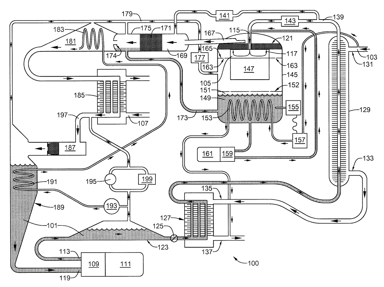
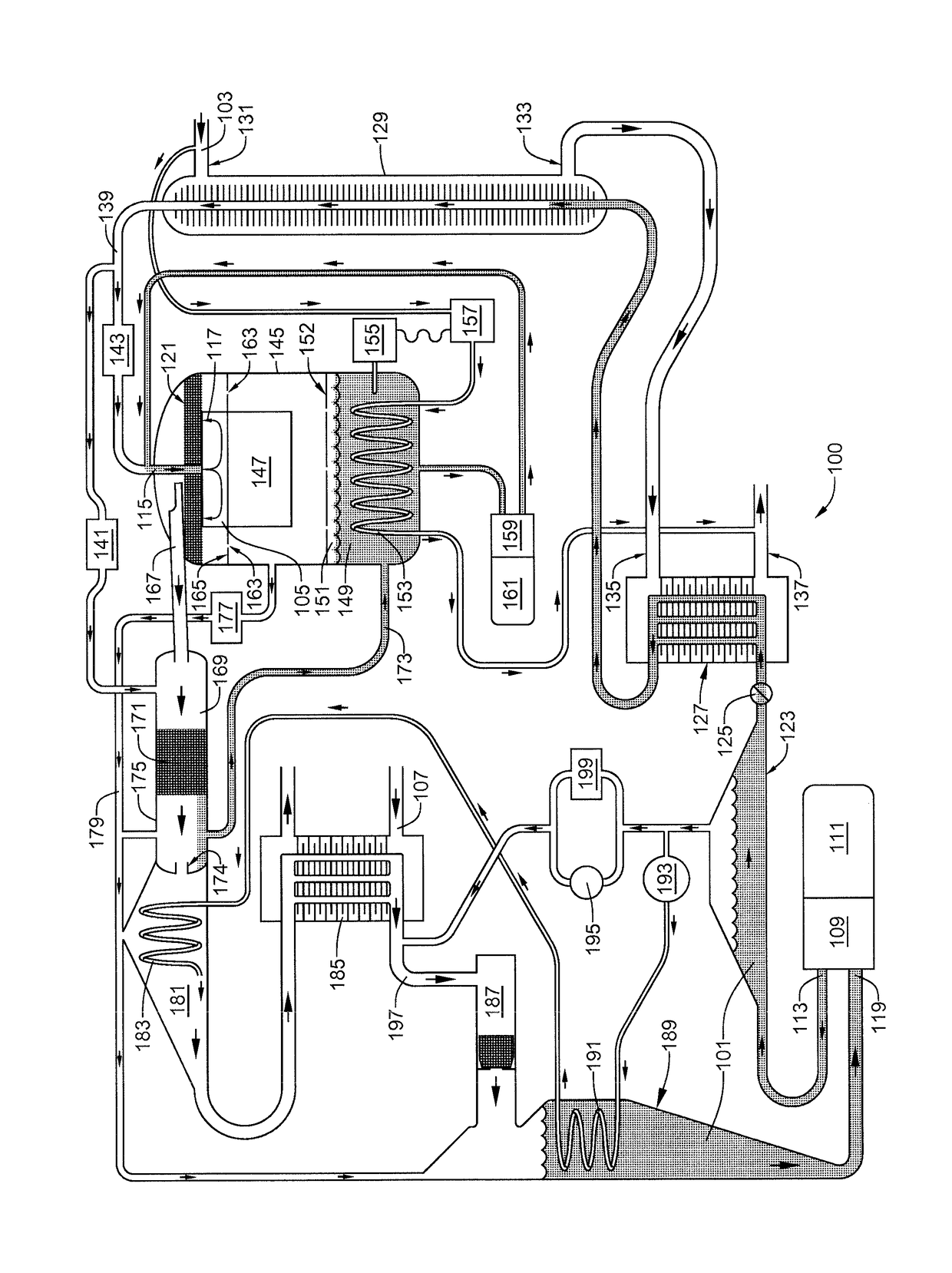
[0035]The invention will now be described with reference to FIG. 1, which shows the ordered arrangement of equipment required to implement the improved organic Rankine cycle decompression heat engine 100. The improved heat engine 100, which employs a highly specialized organic Rankine cycle, provides a sealed, closed-loop path for an organic refrigerant 101 having a...


PUM


Abstract

An improved heat engine that includes an organic refrigerant exhibiting a boiling point below −35° C.; a heat source having a temperature of less than 82° C.; a heat sink; a sealed, closed-loop path for the organic refrigerant, the sealed, closed-loop path having both a high-pressure zone that absorbs heat from the heat source, and a low-pressure zone that transfers heat to the heat sink; a positive-displacement decompressor providing a pressure gradient through which the organic refrigerant in the gaseous phase flows continuously from the high-pressure zone to the low-pressure zone, the positive-displacement decompressor extracting mechanical energy due to the pressure gradient; and a positive-displacement hydraulic pump, which provides continuous flow of the organic refrigerant in the liquid phase from the low-pressure zone to the high-pressure zone, the hydraulic pump and the positive-displacement decompressor maintaining a pressure differential between the two zones of between about 20 to 42 bar.

Description

CROSS-REFERENCE TO RELATED APPLICATIONS[0001]This application is a national phase entry under 35 U.S.C. §371 of International Patent Application PCT / US2014 / 014965, filed Feb. 5, 2014, designating the United States of America and published in English as International Patent Publication WO 2014 / 124061 A1 on Aug. 14, 2014, which claims the benefit under Article 8 of the Patent Cooperation Treaty and under 35 U.S.C. §119(e) to U.S. Provisional Patent Application Ser. Nos. 61 / 841,610, filed Jul. 1, 2013, 61 / 817,862, filed Apr. 30, 2013, and 61 / 761,115, filed Feb. 5, 2013. The disclosures of each of these applications are hereby incorporated herein in their entireties by this reference.TECHNICAL FIELD[0002]This invention relates generally to organic Rankine cycle systems and, more particularly, to an improved heat engine that includes an organic refrigerant exhibiting a boiling point below −35° C.BACKGROUND[0003]The Rankine cycle is a thermodynamic cycle that converts heat into work. The ...

Claims


Application Information

Patent Timeline
Patent Type & Authority Patents(United States)
IPC IPC(8): F01K25/04F01K3/26F01K23/08F01K25/10F01K7/36
CPCF01K25/04F01K3/262F01K7/36F01K23/08F01K25/10F01K25/103Y02E20/16
Inventor JOHNSON, KEITH STERLINGNEWMAN, COREY JACKSON
Owner HEAT SOURCE ENERGY
Why Eureka
Try Eureka