Fibre optic sensing
a technology of fiber optics and sensing, applied in the direction of converting sensor output, structural/machine measurement, analysing solids using sonic/ultrasonic/infrasonic waves, etc., can solve the problem of detectable change in optical radiation properties, and achieve the effect of being ready to calibra
- Summary
- Abstract
- Description
- Claims
- Application Information
AI Technical Summary
Benefits of technology
Problems solved by technology
Method used
Image
Examples
example 1
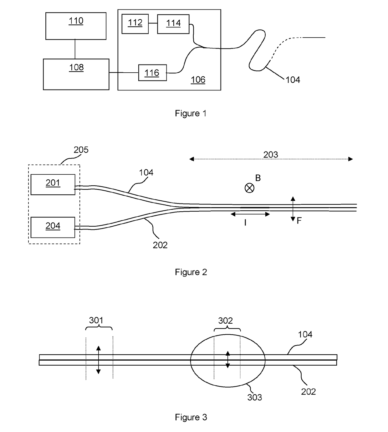
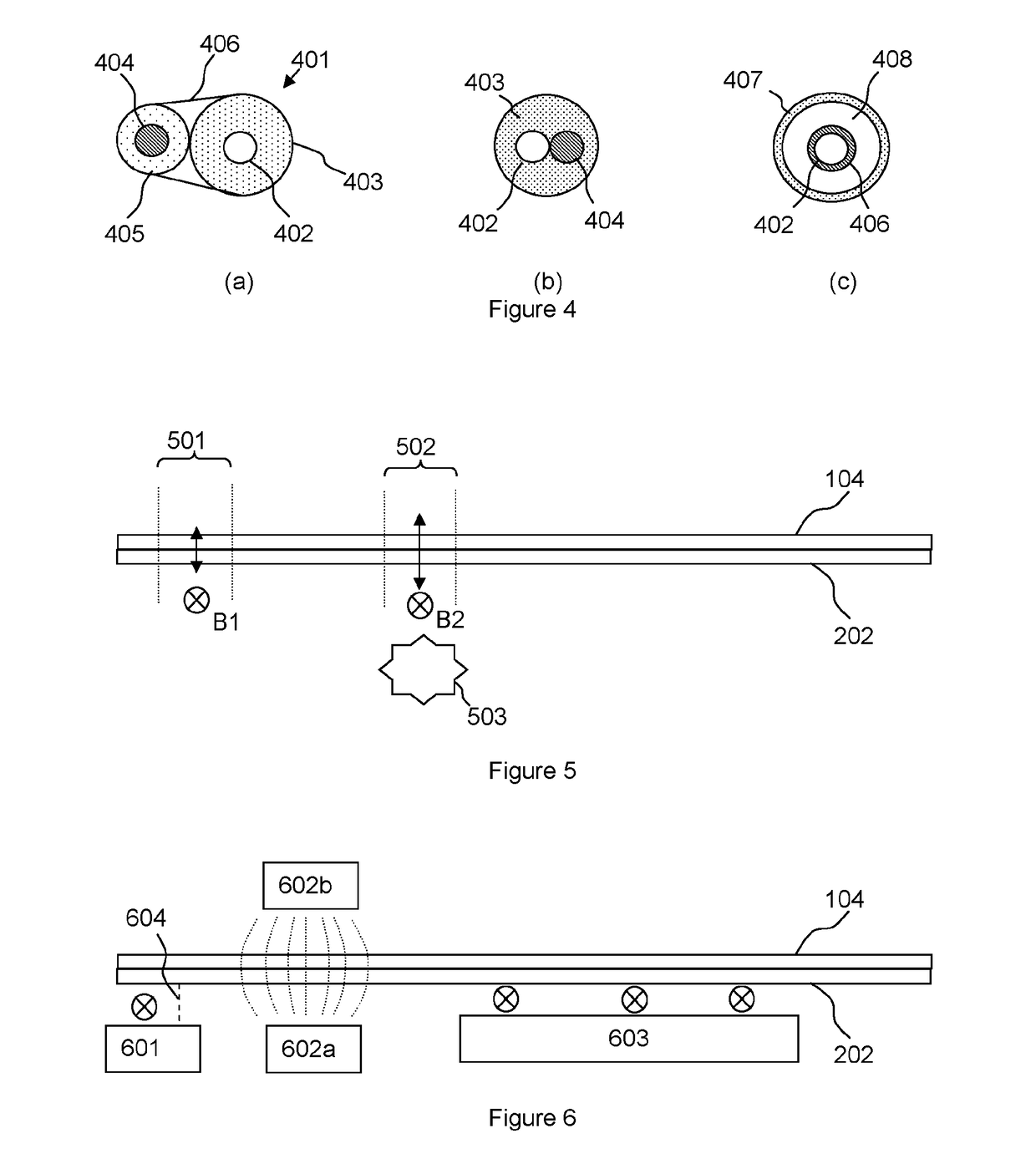
[0158]To demonstrate the principles of the present invention a 35 m length of fibre optic cable was bonded to a copper conductor. A frequency generator and amplifier were attached to the conductor to enable an electrical signal to be passed through the conductor. The fibre optic cable with bonded conductor was then orientated (magnetic) east-west on land, north-south on land and north-south in water for tests using the earth's magnetic field. The local angle of dip for the magnetic field was about 63°. A variety of current frequencies and amplitudes were fed into the conductor and the optical signal recorded. The current signal used was both continuous wave and frequency sweeps. When the fibre optic cable was in the north-south orientation recordings were made with the fibre optic cable lying on the surface of the ground, lightly covered in dry sand and with large pieces of ferrous metal in close proximity. Further tests were done using permanent magnets.
[0159]The results showed tha...
example 2
[0161]To test that this measurement signal does indeed result from the interaction of the local magnetic field, i.e. the earth's magnetic field in the tests described above, a number of additional tests were performed in a laboratory setting.
[0162]Test 1—The measurement signal on the fibre was measured with an alternating current flowing through the copper conductor attached to the fibre optic cable and the Lorentz force was calculated assuming its origin to be due to the interaction of the current and the magnetic field of the earth.
[0163]Test 2—Permanent magnets were then used to increase the strength of the local magnetic field. The amplitude of the signal for a given AC electrical signal was found to increase with increasing magnetic field strength (resolved perpendicular to the axis of the fibre).
[0164]Test 3—The time varying current in the conductor attached to the fibre optic cable was then replaced with a steady current, and the DC magnetic field was augmented by an AC field...
example 3
[0166]A clear change in the signal was also seen when large pieces of ferrous metal were placed near the fibre thus indicating the suitability for ferrous object detection. Using the same test set-up as Example 1 results were obtained over a period of 2 minutes while a 7 amp RMS alternating current was flowing in the conductor. For the first minute a 6 m long I-section mild steel beam was kept at a distance of 10 m from the fibre. Halfway through the period the beam was quietly lifted to within about 50 mm of the fibre optic cable. FIG. 10 shows a spectrogram for a single sensing portion of optical fibre at the location where the steel beam was introduced. FIG. 10 shows the variation in power distribution of the measurement signal in frequency against time. Intensity would normally be represented by colour.
[0167]It can be seen from FIG. 10 that there is a clear component 1001 of the measurement signal detected at about 53 Hz and also another 1002 at about 106 Hz. These signals (whic...
PUM
 Abstract
Description
Claims
Application Information
 - R&D
- Intellectual Property
- Life Sciences
- Materials
- Tech Scout
- Unparalleled Data Quality
- Higher Quality Content
- 60% Fewer Hallucinations
Browse by: Latest US Patents, China's latest patents, Technical Efficacy Thesaurus, Application Domain, Technology Topic, Popular Technical Reports.
© 2025 PatSnap. All rights reserved.Legal|Privacy policy|Modern Slavery Act Transparency Statement|Sitemap|About US| Contact US: help@patsnap.com


