Controlling the uniformity of PECVD deposition

a technology of uniformity and pecvd, applied in the field of coating surfaces, can solve the problems of non-uniform surface chemistry at the molecular level, damage to stored materials, and failure of syringes in the market, and achieve the effect of improving uniformity, density, or density

Active Publication Date: 2017-09-19
SI02 MEDICAL PRODS
View PDF1274 Cites 9 Cited by
  • Summary
  • Abstract
  • Description
  • Claims
  • Application Information

AI Technical Summary

Benefits of technology

[0023]An aspect of the invention is a method of plasma modifying a workpiece, for example a syringe barrel or cartridge barrel, having a surface to be treated. “Plasma” in this sense refers to an energized state of matter similar to gas in which a certain portion of the particles of matter are ionized. To carry out the method, plasma is provided in or near the surface under conditions effective for plasma modification of the surface of the workpiece. At least part of the time while providing plasma, a magnetic field is provided in or near the plasma. The magnetic field has a position, orientation, and field strength effective to improve the uniformity, density, or both of plasma modification of the surface of the workpiece.
[0026]The magnetic field generator provides a magnetic field in at least a portion of the lumen of a workpiece supported on the workpiece support. The magnetic field has an orientation and field strength effective to improve the uniformity, density, or both of plasma modification of the interior surface of the generally cylindrical wall.

Problems solved by technology

However, the recent advent of costly, complex and sensitive biologics as well as such advanced delivery systems as auto injectors has exposed the physical and chemical shortcomings of glass pharmaceutical packages or other vessels, including possible contamination from metals, flaking, delamination, and breakage, among other problems.
Moreover, glass contains several components which can leach out during storage and cause damage to the stored material.
The heterogeneous nature of borosilicate glass creates a non-uniform surface chemistry at the molecular level.
Many proteins and other biologics must be lyophilized (freeze dried), because they are not sufficiently stable in solution in glass vials or syringes.
Additionally, the silicone oil coating or layer is often non-uniform, resulting in syringe failures in the market.
Glass pharmaceutical packages or other vessels are prone to breakage or degradation during manufacture, filling operations, shipping and use, which means that glass particulates may enter the drug.
Glass-forming processes do not yield the tight dimensional tolerances required for some of the newer auto-injectors and delivery systems.
Although plastic is superior to glass with respect to breakage, dimensional tolerances and surface uniformity, its use for primary pharmaceutical packaging remains limited due to the following shortcomings:
The permeability of plastics to gases can be significantly greater than that of glass and, in many cases (as with oxygen-sensitive drugs such as epinephrine), plastics previously have been unacceptable for that reason.
This can be detrimental to the shelf life of a solid (lyophilized) drug.
Alternatively, a liquid product may lose water in an arid environment.
These compounds can contaminate the drug and / or negatively impact the drug's stability.

Method used


Image

  • Controlling the uniformity of PECVD deposition
  • Controlling the uniformity of PECVD deposition
  • Controlling the uniformity of PECVD deposition

Examples


working examples

Comparative Example 1

Thickness Profile for pH-Protective Coating or Layer

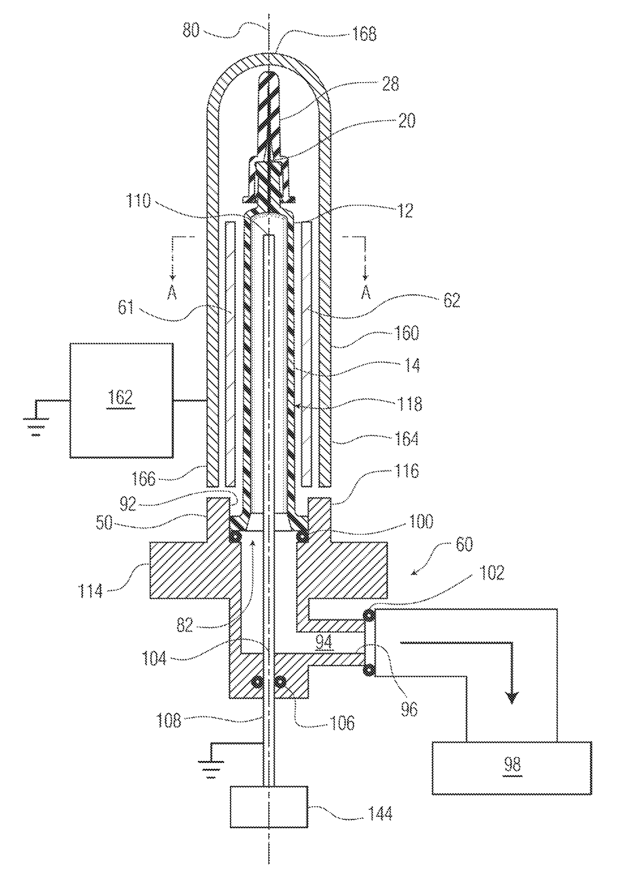
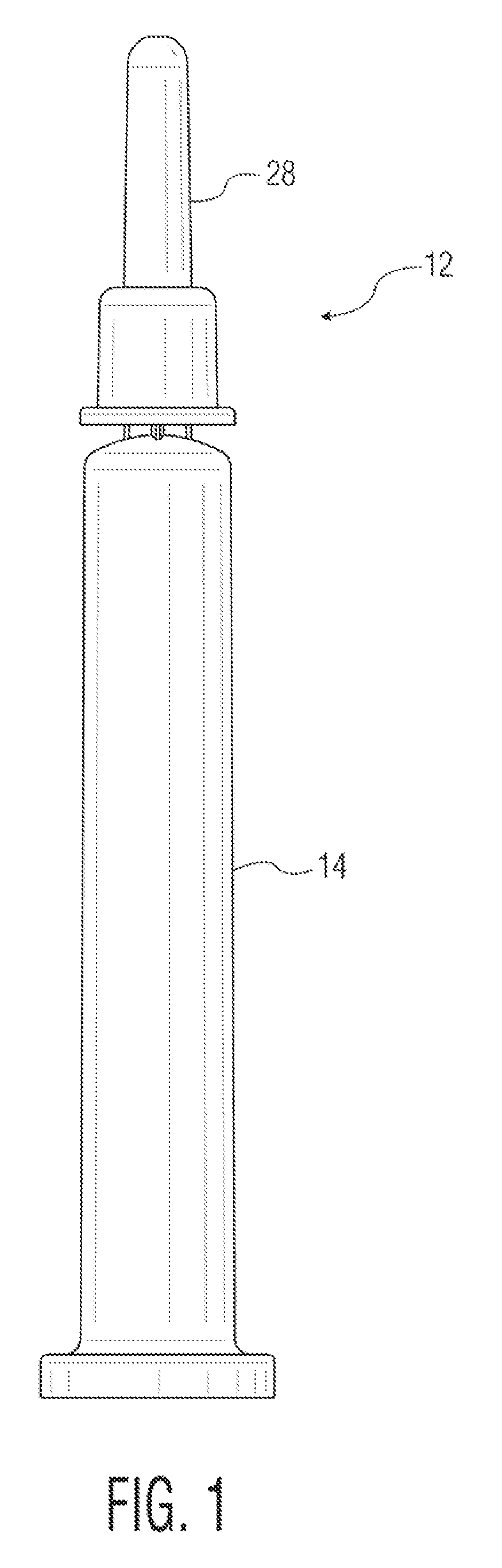
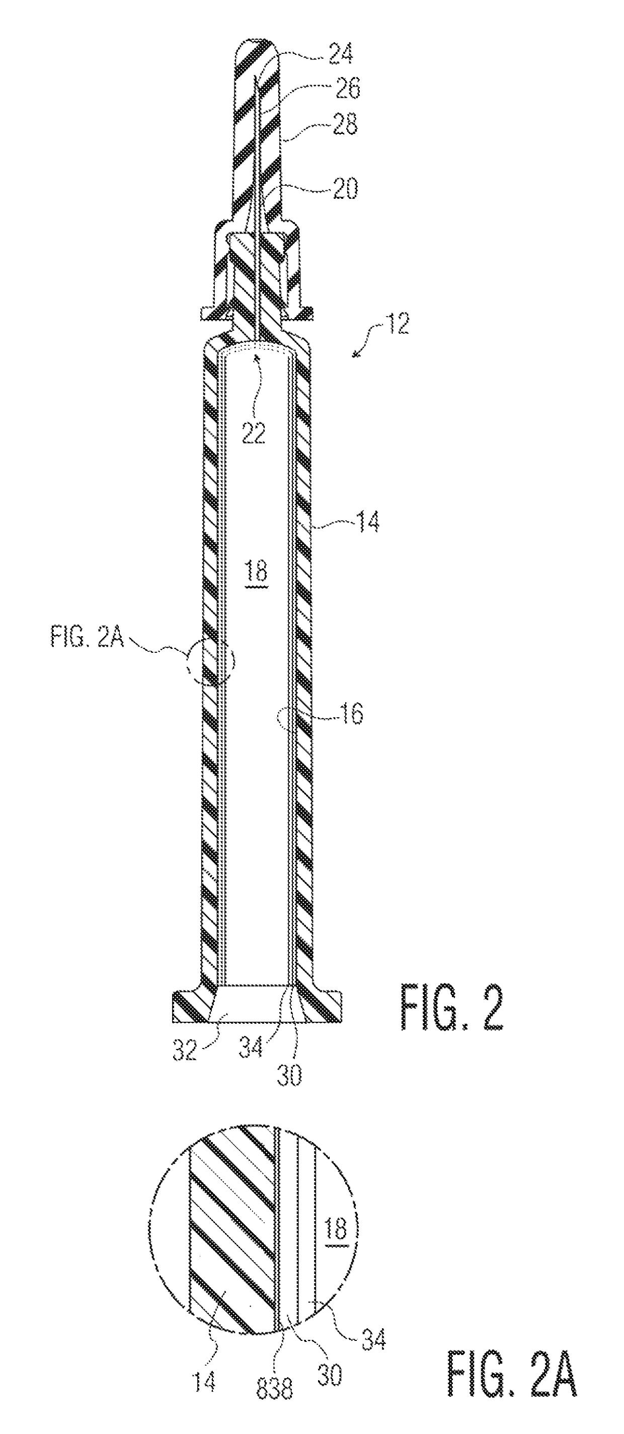
[2240]A pH protective coating (e.g. 34) was applied to the surface (16) of the wall of a syringe. The gas inlet used was provided with the 90-degree perforation pattern shown in FIG. 26. The external electrode was a solid metallic tube. The protocol provided above was generally followed, using 30 Watts of RF energy, OMCTS as a precursor at a flow rate of 2 sccm, argon as a diluent at a flow rate of 20 sccm, oxygen gas as an oxidizing gas at a flow rate of 0.5 sccm, and a continuous plasma energization time of 10 sec. No magnets were used in this example.

[2241]The shelf life or rate of dissolution of the pH protective coating in 0.1 M KOH was measured, and found to be 127 days for the complete coating. A plot of the coating thickness as a function of the position on a cylindrical portion of the syringe barrel is provided as FIG. 30. The plot shows a region of very thick deposition at about 50 degrees around the ...

example 2

Thickness Profile for pH-Protective Coating or Layer

[2246]A pH protective coating (e.g. 34) was applied to the surface (16) of the wall of a syringe. The gas inlet used was provided with the 120-degree or triangular perforation pattern shown in FIG. 27. The protocol provided above was generally followed, using 20 Watts of RF energy, OMCTS as a precursor at a flow rate of 2 sccm, argon as a diluent at a flow rate of 20 sccm, oxygen gas as an oxidizing gas at a flow rate of 0.5 sccm, and a continuous plasma energization time of 5 sec. A stationary quadrupole magnet array using ceramic magnets, generally as shown in FIGS. 4-5, was used, as was a wire mesh electrode.

[2247]The shelf life or rate of dissolution of the pH protective coating in 0.1 M KOH was measured. The coating did not dissolve in standard 0.1 M KOH. A plot of the coating thickness as a function of the position on a cylindrical portion of the syringe barrel is provided as FIG. 31. The plot shows more uniform deposition of...

example 3

Thickness Profile for pH-Protective Coating or Layer

[2251]A pH protective coating (e.g. 34) was applied to the surface (16) of the wall of a syringe. The gas inlet used was provided with the 45-degree or spiral perforation pattern shown in FIG. 28. The protocol provided above was generally followed, using 20 Watts of RF energy, OMCTS as a precursor at a flow rate of 2 sccm, argon as a diluent at a flow rate of 20 sccm, oxygen gas as an oxidizing gas at a flow rate of 0.5 sccm, and a continuous plasma energization time of 10 sec. A stationary quadrupole magnet array using neodymium-iron-boron (NDFeB or neodymium) magnets, generally as shown in FIGS. 4-5, was used, as was a wire mesh electrode.

[2252]A plot of the coating thickness as a function of the position on a cylindrical portion of the syringe barrel is provided as FIG. 32. The plot shows more uniform deposition of the coating, with isolated regions of thicker deposition across the height at about 0 and 180 degrees around the ci...


PUM

PropertyMeasurementUnit
thicknessaaaaaaaaaa
temperaturesaaaaaaaaaa
pressureaaaaaaaaaa

Abstract

A method and apparatus for plasma modifying a workpiece such as a syringe barrel, cartridge barrel, vial, or blood tube is described. Plasma is provided within the lumen of the workpiece. The plasma is provided under conditions effective for plasma modification of a surface of the workpiece. A magnetic field is provided in at least a portion of the lumen. The magnetic field has an orientation and field strength effective to improve the uniformity of plasma modification of the interior surface of the generally cylindrical wall. A vessel made according to the process or using the apparatus described above. A pharmaceutical package comprising the syringe barrel or vial containing a pharmaceutical preparation, secured with a closure.

Description

[0001]The priority of the following U.S. Provisional patent applications is claimed: Ser. No. 61 / 800,660, filed Mar. 15, 2013; Ser. No. 61 / 747,584, filed Dec. 31, 2012; Ser. No. 61 / 732,180, filed Nov. 30, 2012. These priority applications are all incorporated here by reference in their entirety to provide continuity of disclosure.[0002]Patent application Ser. No. 12 / 779,007, filed May 12, 2010, now U.S. Pat. No. 7,985,188; PCT / US11 / 36097, filed May 11, 2011; PCT / US12 / 64489, filed Nov. 9, 2012; 61 / 558,885, filed Nov. 11, 2011; 61 / 636,377, filed Apr. 20, 2012; 61 / 645,003, filed May 9, 2012; 61 / 713,435, filed Oct. 12, 2012; 61 / 716,381, filed Oct. 19, 2012; and 61 / 732,180, filed Nov. 30, 2012, are all incorporated here by reference in their entirety.FIELD OF THE INVENTION[0003]The present invention relates to the technical field of coated surfaces, for example interior surfaces of pharmaceutical packages or other vessels for storing or other contact with fluids. Examples of suitable flu...

Claims


Application Information

Patent Timeline
Patent Type & Authority Patents(United States)
IPC IPC(8): A61M5/31C23C16/40C23C16/04C23C16/50
CPCA61M5/3129C23C16/045C23C16/402C23C16/50
Inventor WEIKART, CHRISTOPHERCLARK, BECKY L.STEVENSON, ADAMABRAMS, ROBERT S.BELFANCE, JOHN
Owner SI02 MEDICAL PRODS
Why Eureka
Try Eureka