High efficiency, large scale desalination system

a desalination system and high efficiency technology, applied in the direction of specific water treatment objectives, separation processes, evaporation, etc., can solve the problems of increasing environmental hazards to the ocean ecosystem, affecting the efficiency of desalination systems, and affecting the quality of water supply, so as to reduce the overall energy requirements, and improve the effect of distillation efficiency

Active Publication Date: 2017-09-26
FLO ONICS LLC
View PDF27 Cites 6 Cited by
  • Summary
  • Abstract
  • Description
  • Claims
  • Application Information

AI Technical Summary

Benefits of technology

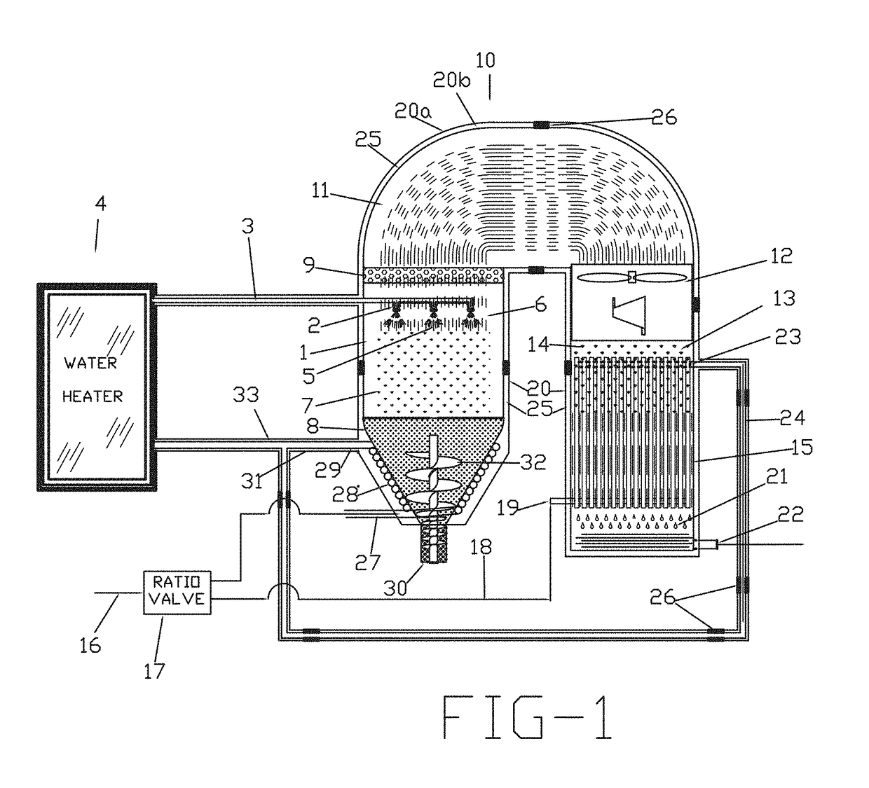
[0021]In one embodiment, the present invention is directed towards a desalination system for substantially increasing the efficiency of the distillation of ocean and brackish water by continuously reusing heat energy to reduce the overall energy requirements, comprised of basic assemblies, including an evaporation chamber, a vapor transfer assembly, and a condensing chamber, that are surrounded by a, double wall assembly comprised of a first and second wall, wherein the space between the first and second wall is placed under low partial vacuum to maintain very low conductive and convection heat loss. An external water heater source feeds heated input sea water into the evaporation chamber through a plurality of spray nozzles, which transforms the sea water into droplet-mist that flash vaporize into a density-saturated vapor. The density-saturated vapor is drawn into the condenser by a vacuum pump assembly. The solids that remain from the flash vaporization fall to the bottom of the evaporation chamber. Any droplet-mist that does not vaporize is prevented from entering the vapor transfer assembly by a demister. The density-saturated vapor is discharged through the vacuum pump assembly and is forced into the condensing chamber located below the vacuum pump assembly. The condenser is then continuously cooled by intake sea water distributed by a ratio valve through an intake channel into a heat-exchanger port. This condenses the liquid-vapor into pure liquid distilled water. Concurrently, the intake sea water is heated by its contact with the heat exchanger. The heated intake sea water is then transferred to the external water heater source through a vacuum insulated channel to be fed back into the evaporation chamber.

Problems solved by technology

In many of the regions where the world population is growing most rapidly, the needed fresh water is not available.
However, present day desalination systems are energy intensive.
Returning concentrated brine solution to the ocean presents a continually escalating environmental hazard to the ocean ecosystem.
The true cost of household fresh water is difficult to assess due to government subsidies, transfer cost and variations in local energy and labor cost.
Another environmental issue involves seawater intakes that can only be addressed in connection with site location of the desalination system.
Both technologies are energy intensive, and both convert about 50% of the input seawater into fresh drinkable water, discharging the remaining brine solution back into the ocean, which results in an ever increasing environmental problem.
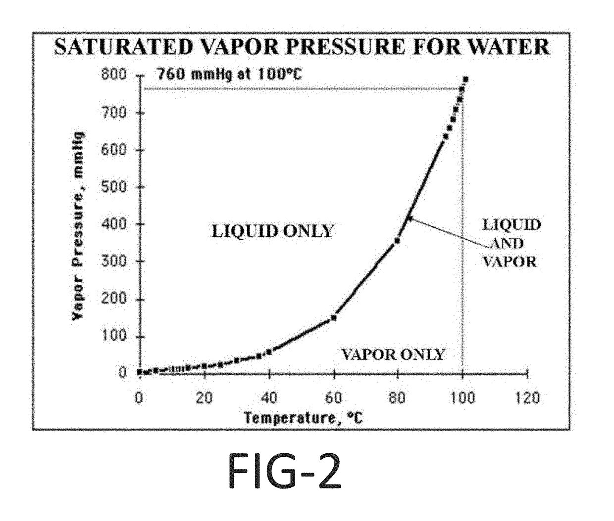
Although seawater can be evaporated at low temperatures by decreasing pressure (partial vacuum), the decreasing temperature results in an exponential decrease in the Vapor Saturation Density.
Therefore, large quantities of vapor must be transferred to recover significant quantities of distilled liquid, which places much higher energy and costs requirements upon the system.
For a filtration process to recover and reuse the energy would require transforming from one form of energy to another (e.g., electrical to pressure) resulting in high entropy.
The process cannot extract dry solids from seawater.
Therefore, there is still a need to create an efficient desalination that results in operational cost equal to, or less than, conventional ground water supplies.

Method used


Image

  • High efficiency, large scale desalination system
  • High efficiency, large scale desalination system
  • High efficiency, large scale desalination system

Examples


Embodiment Construction

[0048]The detailed description set forth below in connection with the appended drawings is intended as a description of presently-preferred embodiments of the invention and is not intended to represent the only forms in which the present invention may be constructed or utilized. The description sets forth the functions and the sequence of steps for constructing and operating the invention in connection with the illustrated embodiment. It is to be understood, however, that the same or equivalent functions and sequences may be accomplished by different embodiments that are also intended to be encompassed within the spirit and scope of the invention.

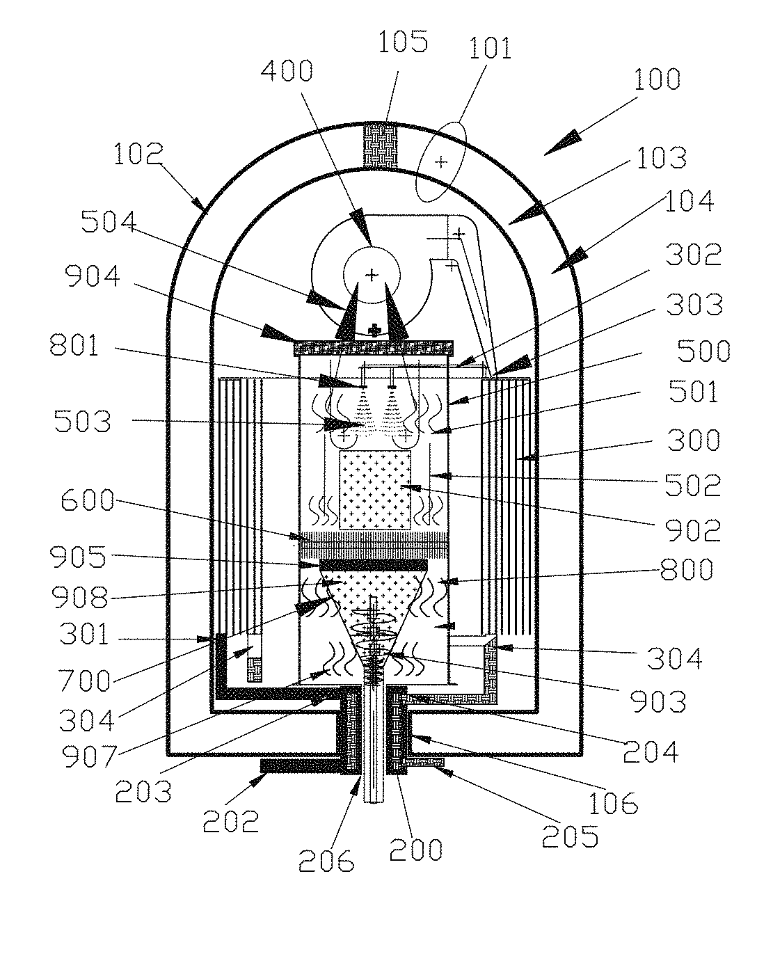
[0049]Referring to the drawings, FIG. 1 is a representative view of an embodiment of the desalination system 10 showing all of the basic assemblies and plumbing surrounded by a first wall 20a and secondary wall 20b of a double wall. The space 25 between the first wall 20a and the secondary wall 20b is under low partial vacuum, between 0.001...


PUM

PropertyMeasurementUnit
saturated vapor densityaaaaaaaaaa

Abstract

An apparatus and method for the distillation of ocean and brackish water that includes a means for using the ambient temperatures of seawater and air to continually transfer the heat energy, from the outer perimeters of the system, back into the, centrally located, evaporation chamber and insulation for preventing heat from escaping to the atmosphere. The insulation comprises a first and second wall surrounding the basic assemblies of a desalination system in which the space between the first and second wall is under low partial vacuum and is partially filled with an insulation material for structural support. The system provides a feed through means that prevent heat transfer through the structural connections between the first and second walls. The system provides an evaporation system for flash evaporation by atomizing the input contaminated water, preheated by the heat of condensation into very small liquid droplets, which are then sprayed into a stream of hot dry air. The liquid rapidly evaporates leaving behind hot dry solids that is recaptured and used to preheat the input contaminated water.

Description

CROSS REFERENCE TO RELATED APPLICATIONS[0001]This application is a continuation-in-part application of U.S. patent application Ser. No. 12 / 902,011, filed Oct. 11, 2010, entitled “Large Scale insulated Desalination System,” which application is incorporated here in its entirety by this reference.BACKGROUND[0002]The present invention relates primarily to methods of improving the efficiency, reducing environmental issues, and operational and capital costs, of desalination systems. More particularly, to desalination systems that distill brackish or ocean water.[0003]Fresh water is a scant 2.5% of the total global water supply and 69% of that is represented by permanent snow and glaciers. The remaining 97.5% is saltwater. Since 1940, the amount of fresh water used by humanity has roughly quadrupled as the world population doubled. Given the finite nature of the earth's fresh water resources, such a quadrupling of worldwide water use probably cannot occur again. In many of the regions whe...

Claims


Application Information

Patent Timeline
Patent Type & Authority Patents(United States)
IPC IPC(8): C02F1/12C02F1/04B01D1/00B01D1/18B01D1/30B01D5/00B01D1/28C02F1/14C02F1/06C02F103/08
CPCC02F1/12B01D1/0035B01D1/0094B01D1/18B01D1/28B01D1/305B01D5/006C02F1/042C02F1/14C02F1/06C02F2103/08C02F2303/10Y02W10/30Y02A20/124Y02A20/142Y02A20/212
Inventor HAYNES, JOEL
Owner FLO ONICS LLC
Why Eureka
Try Eureka