
Parallel flow cytometer using radiofrequency multiplexing

a flow cytometer and radiofrequency multiplexing technology, applied in the field of parallel flow cytometers, can solve the problems of not being very effective when used with suspension cells, and achieve the effects of improving the cost and simplicity of these systems, increasing throughput, and increasing throughpu

Active Publication Date: 2017-10-10
RGT UNIV OF CALIFORNIA
View PDF5 Cites 85 Cited by
  • Summary
  • Abstract
  • Description
  • Claims
  • Application Information

AI Technical Summary

Benefits of technology

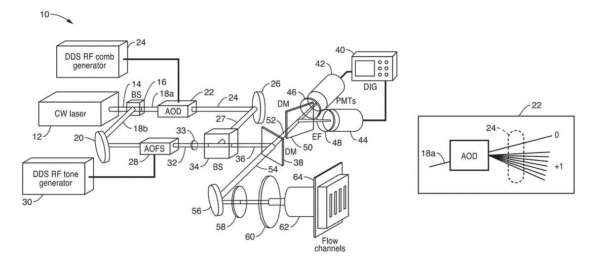
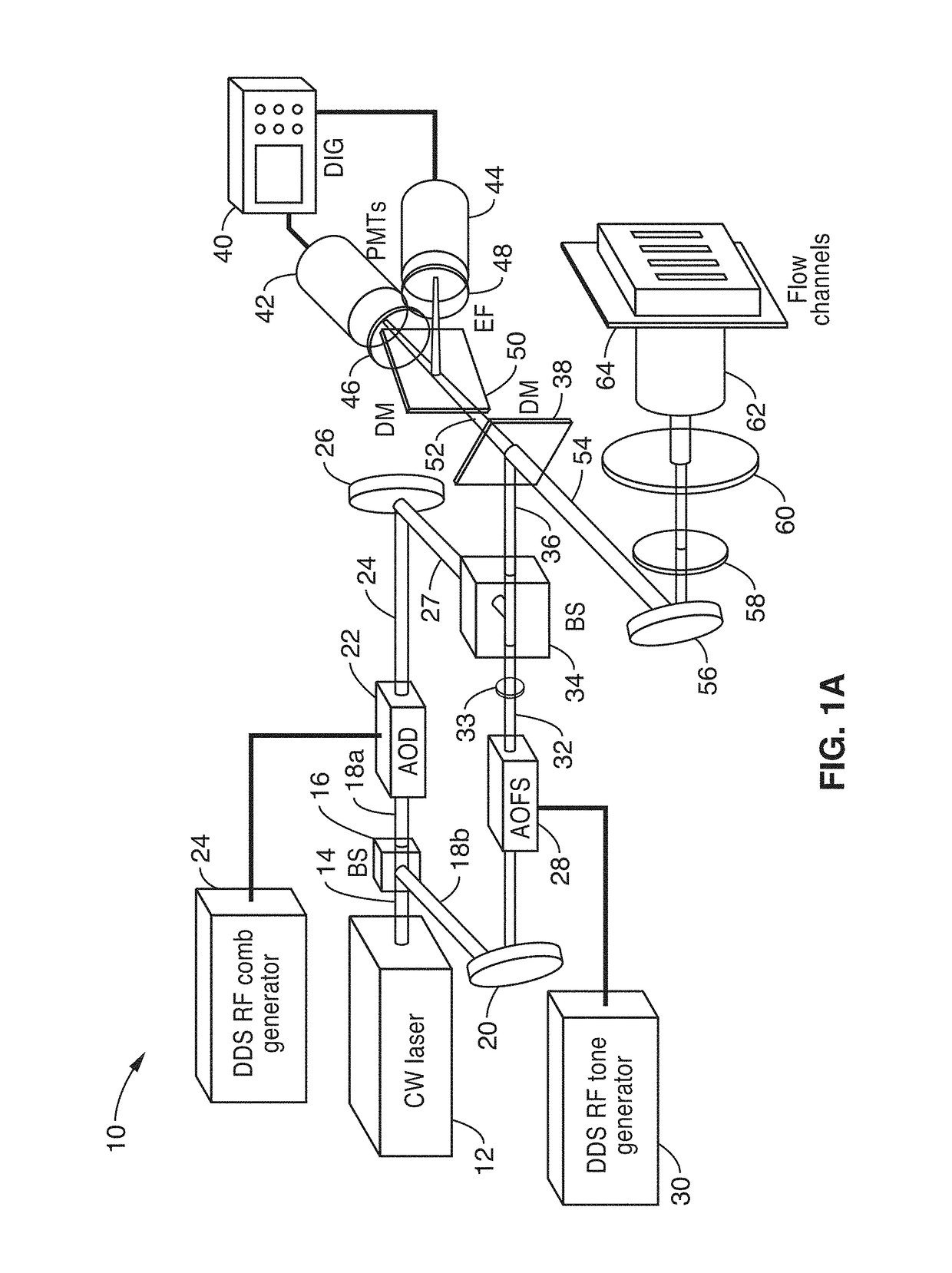
[0019]An optical engine is disclosed for a highly-parallel flow cytometer which improves sample screening throughput by an order of magnitude, such as 200 wells per minute. In at least one embodiment, the disclosed apparatus and method can be integrated with a commercial multi-probe autosampler.
[0020]The disclosed technology drastically reduces both the time and cost requirements of high throughput compound screens using flow cytometry. Inherently, the ability to use multi-parameter flow cytometry provides richer information than instruments, such as plate readers, due to the high content cell-level information provided, and the ability to measure sub-populations within the sample wells. While high content imaging also provides many of these advantages, it is not very effective when utilized with suspension cells, and requires sophisticated image processing and data handling to extract meaningful parameters from samples.

Problems solved by technology

While high content imaging also provides many of these advantages, it is not very effective when utilized with suspension cells, and requires sophisticated image processing and data handling to extract meaningful parameters from samples.

Method used


Image

  • Parallel flow cytometer using radiofrequency multiplexing
  • Parallel flow cytometer using radiofrequency multiplexing
  • Parallel flow cytometer using radiofrequency multiplexing

Examples


Embodiment Construction

[0027]1. Innovation.

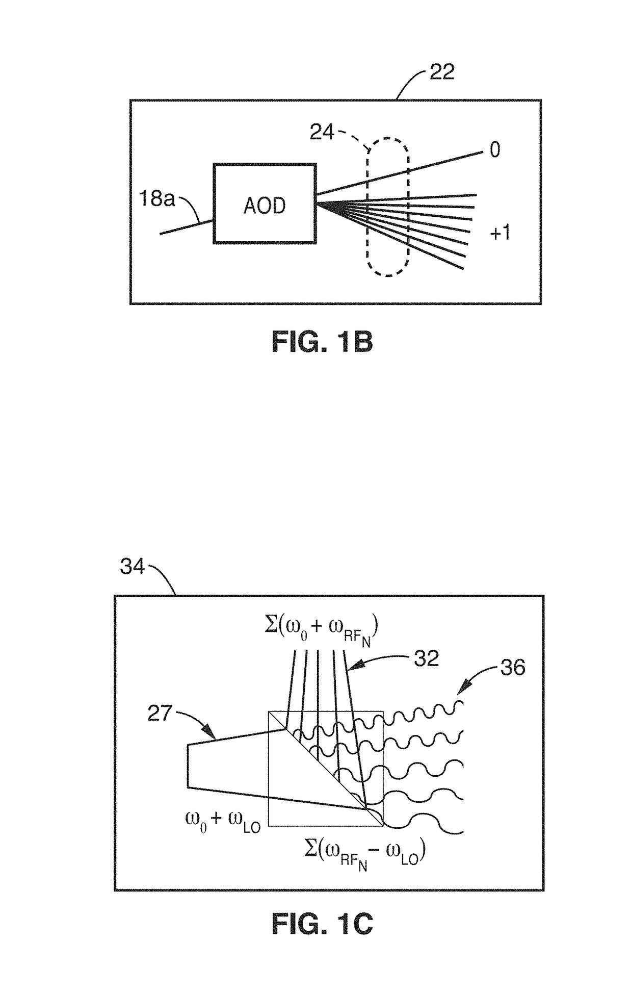
[0028]The present disclosure provides a single cytometer that is capable of sampling and reading a plurality of wells (e.g., 10) in parallel, for enhancing flow cytometry throughput, such as utilized in applications like drug discovery. Although many commercial options for parallel liquid sample sipping / aspiration and handling, there have been no existing instruments that could interrogate multiple cells in parallel at high speed with sufficient optical sensitivity. While several microfluidic approaches to parallel flow cytometry have been demonstrated, these systems employed laser scanning illumination, or silicon high-speed cameras as optical detectors. These demonstrations had two primary limitations: (1) laser scanning does not support parallel analysis of cells flowing at meter / s velocities due to the limited duty cycle of the laser exposure on each channel; (2) silicon cameras although useful for imaging brightly-illuminated scenes at high speed, neither po...


PUM

PropertyMeasurementUnit
velocityaaaaaaaaaa
frequencyaaaaaaaaaa
memory depthaaaaaaaaaa

Abstract

An imaging flow cytometry apparatus and method which allows registering multiple locations across a cell, and / or across multiple flow channels, in parallel using radio-frequency-tagged emission (FIRE) coupled with a parallel optical detection scheme toward increasing analysis throughput. An optical source is modulated by multiple RF frequencies to produce an optical interrogation beam having a spatially distributed beat frequency. This beam is directed to one or more focused streams of cells whose responsive fluorescence, in different frequencies, is registered in parallel by an optical detector.

Description

CROSS-REFERENCE TO RELATED APPLICATIONS[0001]This application is a 35 U.S.C. §111(a) continuation of PCT international application number PCT / US2015 / 021264 filed on Mar. 18, 2015, incorporated herein by reference in its entirety, which claims priority to, and the benefit of, U.S. provisional patent application Ser. No. 61 / 955,137 filed Mar. 18, 2014, incorporated herein by reference in its entirety. Priority is claimed to each of the foregoing applications.[0002]The above-referenced PCT international application was published as PCT International Publication No. WO 2015 / 143041 on Sep. 24, 2015, which publication is incorporated herein by reference in its entirety.STATEMENT REGARDING FEDERALLY SPONSORED RESEARCH OR DEVELOPMENT[0003]This invention was made with Government support under Grant Number W81XWH-10-1-0518, awarded by the U.S. Army, Medical Research and Materiel Command. The Government has certain rights in the invention.INCORPORATION-BY-REFERENCE OF COMPUTER PROGRAM APPENDIX...

Claims


Application Information

Patent Timeline
Patent Type & Authority Patents(United States)
IPC IPC(8): G01N15/14G01N21/64G01N15/10
CPCG01N15/1434G01N21/64G01N21/6428G01N2201/067G01N21/6486G01N2015/1006G01N2021/6421G01N21/6458G01N15/1459G01N2015/1477G01N15/1484G01N33/537
Inventor JALALI, BAHRAMDIEBOLD, ERICBUCKLEY, BRANDON
Owner RGT UNIV OF CALIFORNIA
Learn More