Hybrid ophthalmic interface apparatus

a technology of ophthalmic surgery and interface device, which is applied in the field of ophthalmic laser surgery, can solve the problems of reducing the flexibility of the patient, reducing the degree of ophthalmic surgery, and affecting the patient's recovery, so as to achieve sufficient flexibility and deformation

Active Publication Date: 2017-10-24
AMO DEVMENT
View PDF12 Cites 4 Cited by
  • Summary
  • Abstract
  • Description
  • Claims
  • Application Information

AI Technical Summary

Benefits of technology

[0013]According to the first embodiment, a patient interface for coupling a patient's eye to an ophthalmic surgical laser system comprises a fluid-filled bladder of a flexible material attached to a lower end of a lens cone that is adapted to couple to an ophthalmic laser delivery system. The bladder contains a fixed volume of fluid and has sufficient flexibility to deform upon contact with a patient's eye so as to conform to the cornea. The bladder may define an upper tubular collar and a lower dome-shaped contact portion, wherein the upper collar attaches to a lower ring of the lens cone. The bladder desirably has a wall thickness of between about 25-250 μm, and a refractive index (RI) that is within the range of about 1.35-1.41. To help keep track of patient movement, fiducial markings may be provided on the exterior of the bladder which conform to the cornea when the bladder deforms. For instance, the fiducial markings are lines parallel to the axis of the bladder and lens cone and spaced 90° around the bladder.

Problems solved by technology

However, complications surrounding the use of the microkeratome with a metal blade have resulted in research into improved techniques that are performed exclusively by a laser system.
Despite these advances in laser technology, the use of such systems for ophthalmic surgical procedures remains fraught with substantial mechanical limitations, particularly in the area of developing a stable interface between an incident laser beam and the eye of a patient.
Movement of the eye with respect to the intended focal point of the laser beam can lead to non-optimal results and might result in permanent damage to non-renewable tissue within the eye.
While this technique has provided some benefit, the patient bears a significant burden of minimizing relative motion.
This technique is also less tolerant of any significant gross autonomic reflex motions, e.g., as when the patient might be startled.
However, such systems are inordinately expensive since a second, completely independent optical path is typically provided between a patient's eye and a surgical apparatus in order to accommodate the eye tracking apparatus.
Further expense and complexity is incurred since an eye tracking apparatus requires an additional software component in order to be operative, which software component must be integrated into a laser delivery system.
However, although this assumption may hold true in a large number of cases, it certainly does not have universal application.
The actual establishment of an effective device / corneal interface is an exercise in trial-and-error, resulting in a great deal of frustration to doctor and patient, as well as considerable eye fatigue.
Accordingly, any structure which interfaces between a curved, anterior surface of the cornea and laser delivery system will likely encounter such aberration concerns.

Method used


Image

  • Hybrid ophthalmic interface apparatus
  • Hybrid ophthalmic interface apparatus
  • Hybrid ophthalmic interface apparatus

Examples


first embodiment

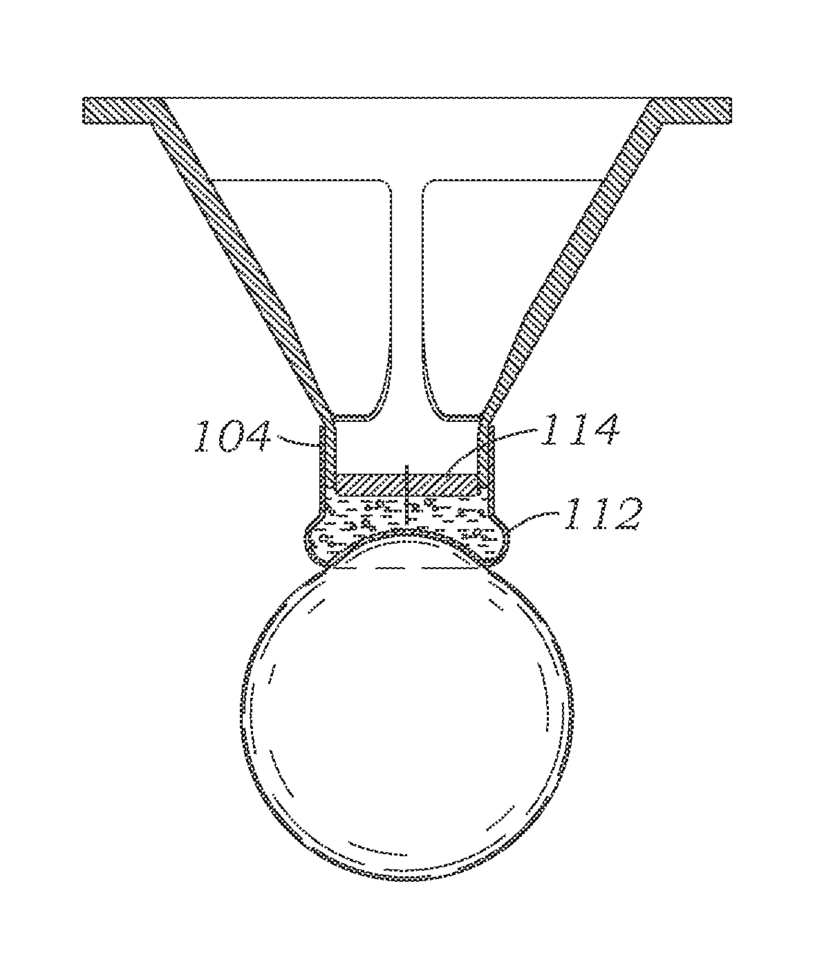
[0055]In a first embodiment, a patient interface 100 seen in FIGS. 4-5 utilizes a compliant liquid-filled bladder 102 attached to the lower apex ring 104 of a lens cone 106. The bladder 102 directly contacts the eye 108, as seen in FIG. 5, and provides some stability thereto during ophthalmic laser surgery. As seen in FIG. 4A, the bladder 102 is desirably made from a thin, compliant plastic or silicone material having an upper tubular collar 110 and a lower dome-shaped contact portion 112. The collar 110 is held on the exterior of the apex ring 104, such as by adhesives or mechanical clamping (not shown) creating a sealed volume above the bladder and below a lens cone glass surface 114.

[0056]The volume within the bladder 102 is partially filled with a transparent fluid having an optical refractive index (RI) that is close to or equal to the RI of the cornea. This RI matching reduces optical distortion experienced by the laser beam when passing through the bladder / cornea interface. I...

second embodiment

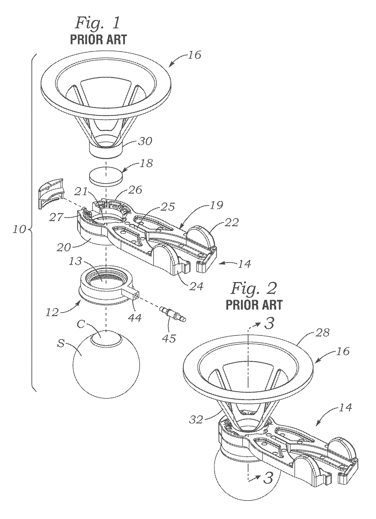
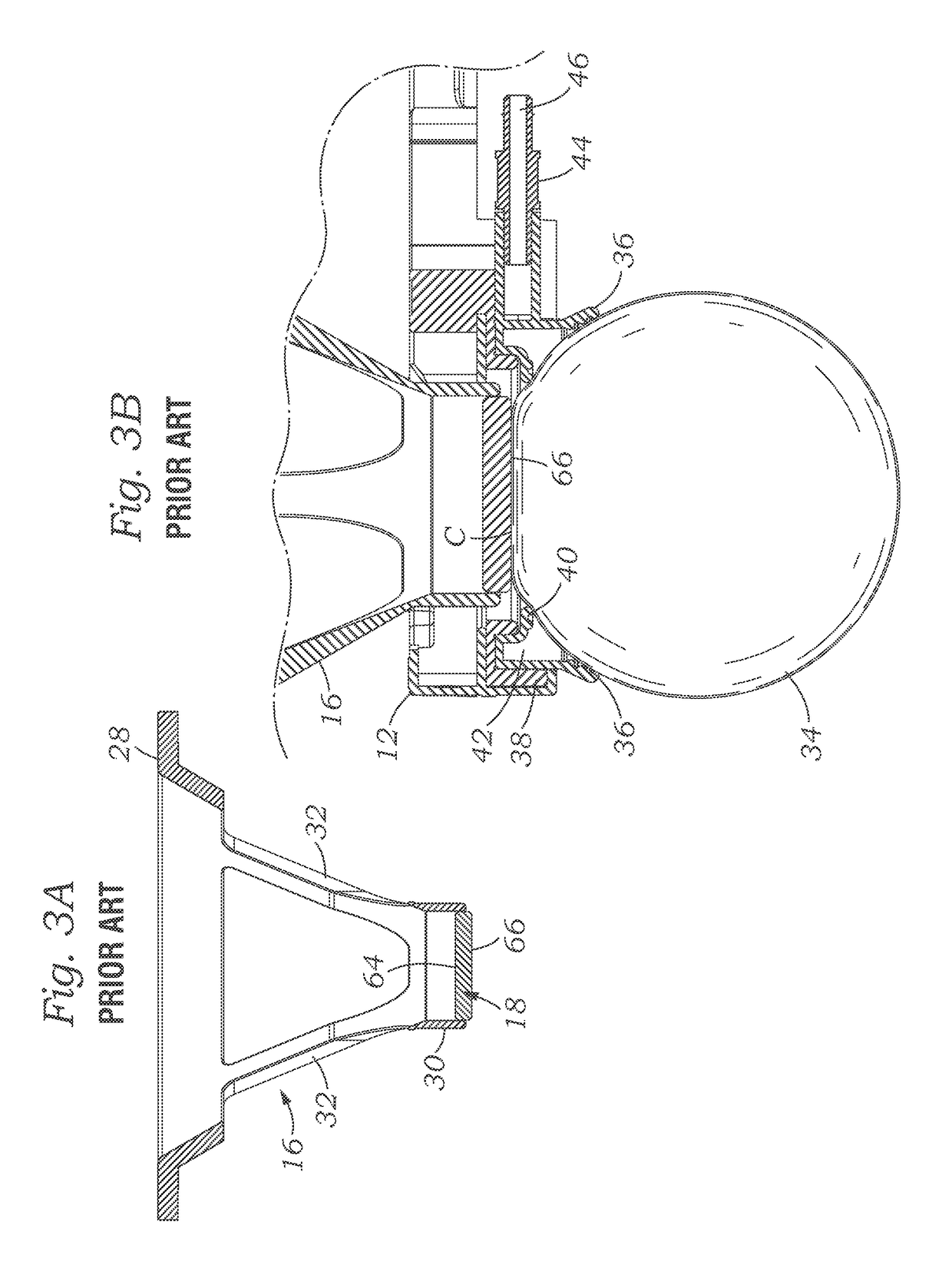
[0064]FIGS. 6-10 illustrate a patient interface for ophthalmic laser surgery including a modified receiver portion 150 and attachment ring 152. The receiver portion 150 is relatively rigid, while the attachment ring 152 is soft and flexible. The attachment ring 152 is similar to the attachment ring 12 described above for the prior art system 10 and provides a vacuum seal against the eye.

[0065]As seen in the exploded view of FIG. 6 and also with reference to the sectional view in FIG. 8, the receiver portion 150 includes an upper housing 160 having a downwardly opening channel 162 that receives therein an annular portion 164 of the attachment ring 152. The ring 152 includes an outer skirt 166 and an inner ring member 168, with an annular vacuum manifold 170 therebetween. The manifold 170 opens to passages that lead to a vacuum port 172. As seen in FIG. 10, lowering the attachment ring 152 to the surface of the eye causes the skirt 166 and ring member 162 form a seal around the annula...


PUM


Abstract

Apparatus and methods are provided for interfacing an ophthalmic surgical laser with an eye using a patient interface (PI). The PI may include a closed, fluid-filled bladder having fiducials that contacts and deforms to the eye. Or, the PI may have an applanation lens with an outer ring portion and an inner concave portion for receiving the apex of the cornea. Another PI features a suction ring with a flexible skirt for contacting the sclera that is non-circular and / or non-planar. A system for injecting an index matching fluid into the area above the eye may also be incorporated. An integrated system includes a co-molded lens cone and attachment ring, with a lens window at the bottom of the lens cone which provides a sealed volume for vacuum-attaching a laser delivery system above the lens cone.

Description

CROSS-REFERENCES TO RELATED APPLICATIONS[0001]This application claims priority to U.S. provisional application No. 61 / 799,981 filed on Mar. 15, 2013, the entire contents of which are incorporated herein by reference.TECHNICAL FIELD[0002]Embodiments of this invention relate to ophthalmic laser surgery and, more particularly, to an ophthalmic interface apparatus used to stabilize the eye of a patient with respect to a laser beam during ophthalmic surgery, a and system and method of interfacing the eye with a surgical laser.BACKGROUND[0003]In recent years, significant developments in laser technology have led to its application in the field of ophthalmic surgery. In particular, laser surgery has become the technique of choice for ophthalmic surgical applications. In certain ophthalmic laser procedures, surgeons use a mechanical device termed a microkeratome to cut a layer of the anterior surface of the cornea in order to expose the underlying corneal stroma to which the laser is applie...

Claims


Application Information

Patent Timeline
Patent Type & Authority Patents(United States)
IPC IPC(8): A61F9/008A61F9/009
CPCA61F9/009A61F9/008
Inventor HEITEL, ROBERT G.VICE, CHARLES C.LEE, HON M.
Owner AMO DEVMENT
Why Eureka
Try Eureka