Method and device for synchronizing entanglement sources for a quantum communication network

a quantum communication network and entanglement source technology, applied in the direction of digital transmission, securing communication, transmission, etc., can solve the problem of limiting the propagation loss of clock pulses to a limit beyond which communication is no longer possible, the final rate of establishment of secret keys is very low, and the optimization of hardware used is considerable. , to achieve the effect of limiting the propagation loss of clock pulses

Active Publication Date: 2017-10-24
UNIV DE NICE SOPHIA ANTIPOLIS +1
View PDF25 Cites 16 Cited by
  • Summary
  • Abstract
  • Description
  • Claims
  • Application Information

AI Technical Summary

Benefits of technology

[0011]This novel concept of fully optical synchronization, which implements a single pulsed source making it possible to deliver an optical clock common to the various entanglement sources of a network, makes it possible to circumvent the additional temporal jitter inherent to optoelectronic devices, and enables the establishment of high-bitrate quantum communication networks over long distances. This novel form of synchronization can be applied whatever the protocol implemented in the quantum communication network, with any number of entanglement sources and users, in pairwise communication between the users.
[0012]According to a variant, said pulsed optical source is a laser emitting pulses at 1550 nm. This wavelength, much used in telecoms, allows the use of low-cost standard telecoms components (components and optical fibers).
[0013]According to a variant, the s

Problems solved by technology

However, although very low, the transmission losses set a limit beyond which communication is no longer possible since the rate of detected photons becomes lower than the noise rate in the detector which remains the main limitation of the signal-to-noise ratio.
A great deal of research work has however pushed these secure links to distances of as much as a few hundred kilometers, at the price however of considerable effort in the optimization of the hardware used and of a very low final rate of establishment of secret keys.
Indeed, the regeneration of the optical signal by means of standard telecoms amplifiers (repeaters) is not possible in quantum communication on account of the so-called “non-cloning” theorem since it would disturb the signal in the same manner as would a spy in seeking to intercept the signal.
However, the same limitation relating to transmission losses applies on each of the segments, and it will not be possible to obtain network lengths of greater than double those obtained in a scheme of the type of that of FIG. 1A.
The experimental realizations of a long distance network of the type of FIG. 1C are thus affected by the technological limitations due mainly to the necessity for synchronization of the entanglement sources situated at large distances.
In particular, the electronic or optoele

Method used


Image

  • Method and device for synchronizing entanglement sources for a quantum communication network
  • Method and device for synchronizing entanglement sources for a quantum communication network
  • Method and device for synchronizing entanglement sources for a quantum communication network

Examples


Embodiment Construction

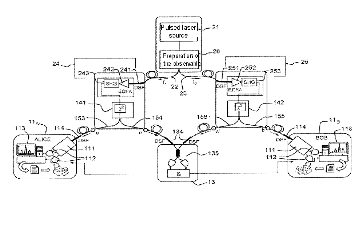
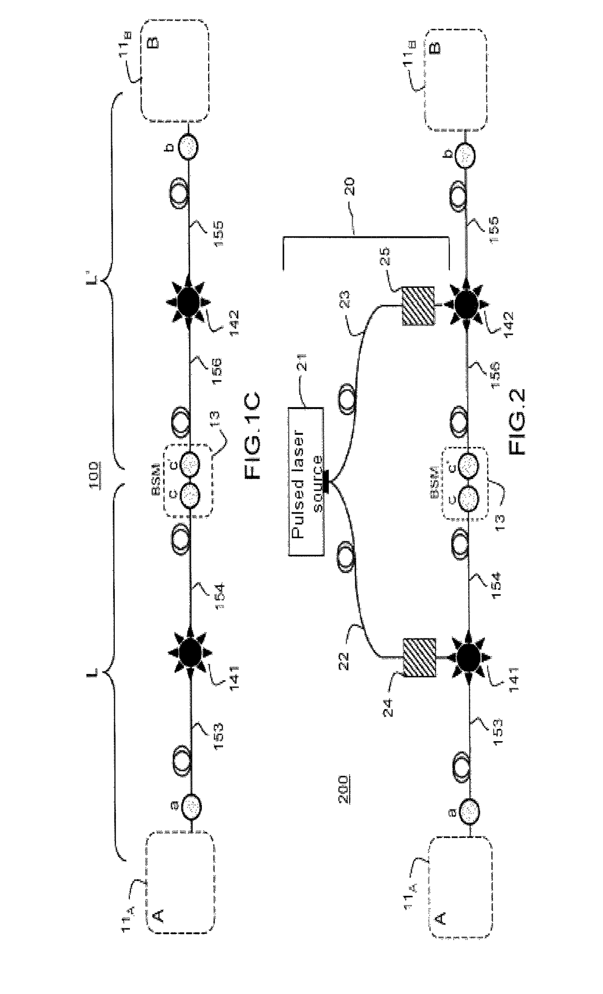
[0028]FIG. 2 describes an exemplary embodiment of a quantum communication network 200 according to the invention between two users Alice and Bob situated at the places A and B. The quantum communication network is, like the network 100 represented in FIG. 1C, a network based on quantum relays. It comprises a plurality of optically pumped entanglement sources 141, 142 and of relay stations 13 disposed between the sources and allowing entanglement teleportation between the users. The generation of the pairs of entangled photons in the entanglement sources is for example obtained by pumping a nonlinear optical component, for example by means of a process of 4-wave mixing by 3rd-order nonlinear effect (χ(3)) in a nonlinear fiber or by spontaneous parametric conversion by 2nd-order nonlinear effect (χ(2)) in a nonlinear crystal, otherwise called SPDC according to the abbreviation standing for the expression “spontaneous parametric down conversion”. In this example, only two entanglement ...


PUM


Abstract

A device and a method for synchronizing entanglement sources with optical pump in a quantum communication network are disclosed. The device includes a pulsed optical source allowing emission of telecom wavelength optical clock pulses distributed in parallel to the entanglement sources to ensure synchronization of the entanglement sources; and for each of the entanglement sources, a frequency conversion device, allowing frequency conversion of the distributed telecom wavelength optical clock pulses to a wavelength adapted to optically pump the entanglement source. The method includes emitting and distributing in parallel, to the entanglement sources, telecom wavelength optical clock pulses; and locally, at each of the entanglement sources, frequency converting the telecom wavelength optical clock pulses to a wavelength adapted to optically pump the entanglement source.

Description

PRIOR ARTTechnical Field of the Invention[0001]The present invention relates to a method and a device for synchronizing entanglement sources for quantum communication network, in particular for long distance quantum communication networks.Prior Art[0002]The objective of quantum communications is to transmit quantum states (or “qubits” according to the abbreviation standing for the expression “quantum bits”) from one place to another. FIG. 1A thus illustrates a simple quantum communication network 100 between a first place A and a second place B allowing two distant interlocutors, traditionally named “Alice” and “Bob”, to establish a secret key with very high confidentiality. In this example, situated at the place A is an emitter 10 comprising a source 101 of single photons (for example a source of atoms with two levels or a quantum dot or a source of heralded single photons, based on nonlinear optics) and an encoding device 102 making it possible to code each bit of the key to be tr...

Claims


Application Information

Patent Timeline
IPC IPC(8): H04B10/25H04B10/70H04L7/00H04L9/08
CPCH04L7/0075H04L9/0852H04B10/70H04B10/25
Inventor TANZILLI, SEBASTIEND'AURIA, VIRGINIAALIBART, OLIVIERMARTIN, ANTHONY CHRISTOPHE MICKAELABONTE, LAURENT
Owner UNIV DE NICE SOPHIA ANTIPOLIS
Why Eureka
Try Eureka