Near-infrared reflective film and near-infrared reflector provided with the same

a technology of reflective film and near-infrared reflector, which is applied in the direction of instruments, lighting and heating apparatuses, optical elements, etc., can solve the problems of increasing interference unevenness in visible light, reducing the wavelength width of light reflecting, and reducing the effect of reflecting sunlight radiant energy, etc., to achieve wide-range reflection and high transmittance

Active Publication Date: 2017-10-31
KONICA MINOLTA INC
View PDF17 Cites 5 Cited by
  • Summary
  • Abstract
  • Description
  • Claims
  • Application Information

AI Technical Summary

Benefits of technology

[0014]By the present invention, a near-infrared reflective film having wide range reflection in the near-infrared region, having a high transmittance in the visible light region, and not having irregularity in visible light reflectivity, and a near-infrared reflector provided with the same were able to be provided.

Problems solved by technology

However, the wavelength width where the light can be reflected decreases, whereby a ripple-shaped reflection sideband is generated around the main reflection and a strong interference reflection is generated in the visible light region adjacent to the near-infrared region.
As the result, the effect of reflecting sunlight radiant energy decreases and the interference unevenness in the visible light increases.

Method used


Image

  • Near-infrared reflective film and near-infrared reflector provided with the same
  • Near-infrared reflective film and near-infrared reflector provided with the same

Examples


example 1

[0127]>

[0128][Production of Sample 1]

[0129](Preparation of Coating Liquid for Forming a High Refractive Layer)

[0130]

[0131]A rutile-type titanium oxide particle was prepared according to the following method as a metal oxide particle used for forming a high refractive index.

[0132]To 10 L (liter) of an aqueous suspension obtained by suspending a titanium dioxide hydrate in water (TiO2 concentration: 100 g / L), 30 L of aqueous sodium hydroxide solution (concentration: 10 mole / L) was added with stirring, and the suspension was heated to 90° C. and matured for five hours, followed by neutralization with hydrochloric acid, filtration and washing with water. In the above-mentioned reaction (treatment), for the titanium dioxide hydrate, those obtained by thermal hydrolysis of aqueous titanium sulfate solution according to a known method was used.

[0133]A base-treated titanium compound was suspended in pure water such that the TiO2 concentration was 20 g / L, and a citric acid was added thereto ...

example 2

[0176][Production of Near-Infrared Reflectors 4 to 11]

[0177]By using the near-infrared reflective films of the samples 4 to 11 produced in Example 1, near-infrared reflectors 4 to 11 were produced. On 5 mm thick, 20 cm×20 cm transparent acrylic resin plates, near-infrared reflective films of samples 4 to 11 were bonded with an acrylic adhesive, respectively to produce near-infrared reflectors 4 to 11.

[Evaluation]

[0178]The near-infrared reflectors 4 to 11 of the present invention produced above can be easily utilized despite the large size thereof. By utilizing the near-infrared reflective film of the present invention, an excellent near-infrared reflectivity was confirmed.


PUM

PropertyMeasurementUnit
transmittanceaaaaaaaaaa
thicknessaaaaaaaaaa
thicknessaaaaaaaaaa

Abstract

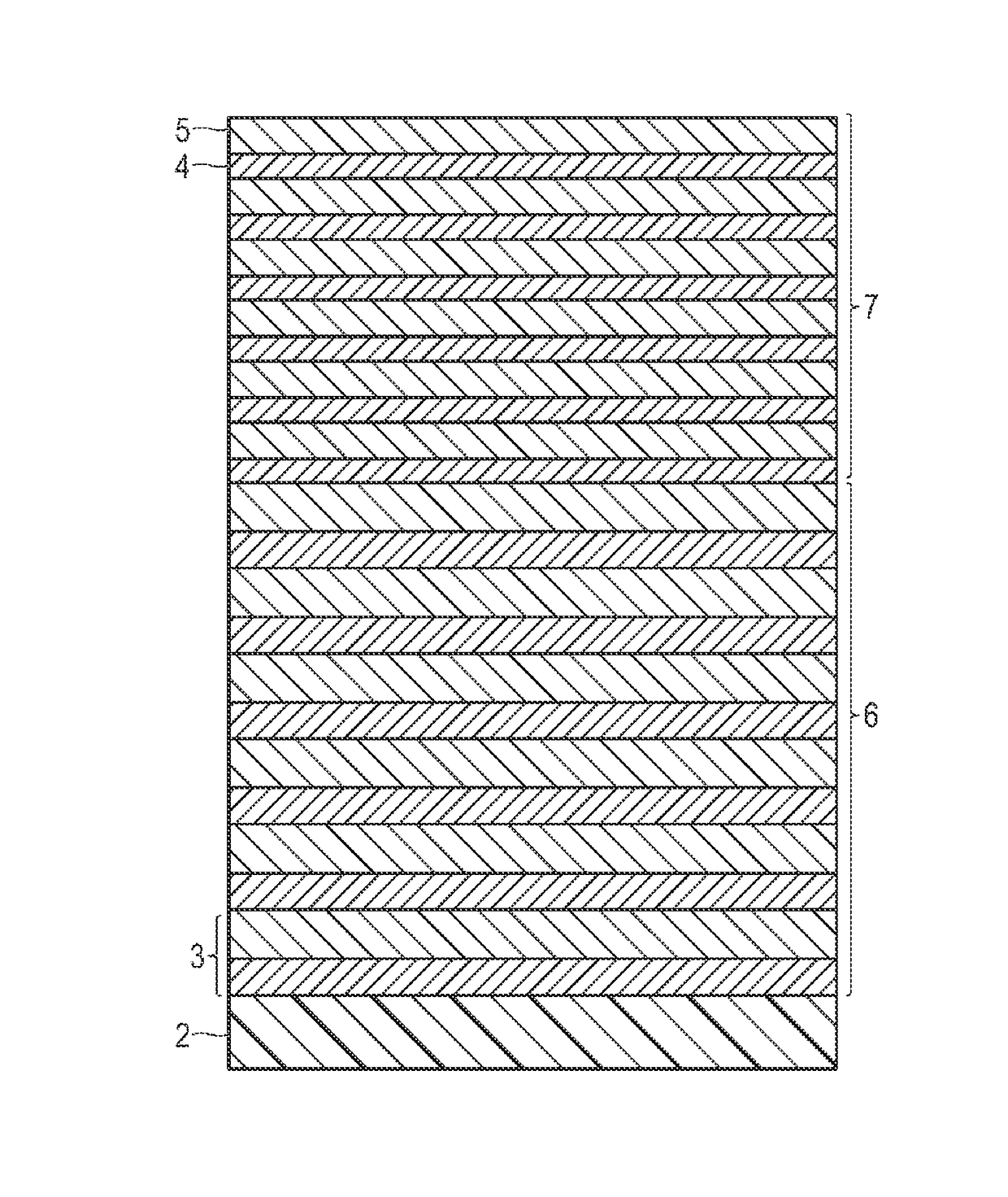
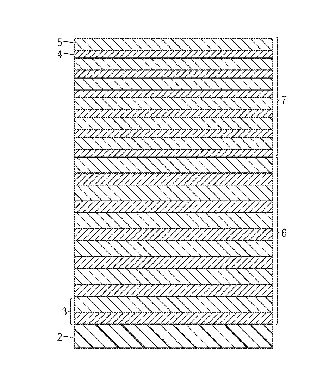
The near-infrared reflective film has, on a base material, a high refractive layer containing a water-soluble polymer and a metal oxide particle having a refractive index higher than the refractive index of the water-soluble polymer, and a low refractive layer containing a water-soluble polymer and a metal oxide particle having a refractive index lower than the refractive index of the water-soluble polymer are alternately laminated individually in two or more layers. The total number of the layers of the high refractive layer and the low refractive layer is n. The total film thickness of the component layers from the region of n / 2 to the base material is Σd1, and the total film thickness of the component layers from the region of n / 2 to the outermost layer is Σd2. The film thickness ratio Σd1 / Σd2 is from 1.05 to 1.80.

Description

CROSS REFERENCE TO RELATED APPLICATION[0001]This is a U.S. National Phase Application under 35 U.S.C. 371 of International Application PCT / JP2011 / 076527, filed Nov. 17, 2011, which claims the priority of Japanese Application No. 2010-274485, filed Dec. 9, 2010, the entire content of both Application are hereby incorporated by reference.TECHNICAL FIELD[0002]The present invention relates to a near-infrared reflective film which has an excellent near-infrared reflecting power and an excellent visible light uniformity, and a near-infrared reflector provided with the same.Technical Field[0003]In recent years, for reducing electric energy for cooling in summertime, energy saving techniques which prevent heat radiant energy of sunlight from entering a room through a windowpane of a house or an office draw attention, and evaluation of a variety of films therefor is seen on the Ministry of the Environment website.[0004]For such films, a variety of methods are proposed such as a method of abs...

Claims


Application Information

Patent Timeline
Patent Type & Authority Patents(United States)
IPC IPC(8): F21V9/04G02B5/28B32B17/10C03C17/42
CPCG02B5/282B32B17/10018B32B17/10761C03C17/42G02B5/287B32B17/10788C03C2217/734
Inventor NAKAJIMA, AKIHISA
Owner KONICA MINOLTA INC
Why Eureka
Try Eureka