Permeable electric thermal resistor foil for vaporizing fluids from single-use mouthpieces with vaporizer membranes

a technology of electric thermal resistor foil and vaporizer membrane, which is applied in the direction of ohmic-resistance heating, tobacco, electrical equipment, etc., can solve the problems of increasing the risk of vaporizing microorganisms and undesired harmful substances during the consumption period, and the loss of quality during the consumption period. , to achieve the effect of optimizing machine processability, reducing

Active Publication Date: 2017-11-14
PHILIP MORRIS PROD SA
View PDF27 Cites 30 Cited by
  • Summary
  • Abstract
  • Description
  • Claims
  • Application Information

AI Technical Summary

Benefits of technology

[0043]Another essential advantage of the invention is that, by varying the geometrical configuration of the thermal resistor foil, e.g. by varying the number of coil windings, the width of the windings and / or the wall thickness of the foil or of the thin sheet, the power of the thermal resistor can be adapted in the best possible way to various substances to be vaporized, which contain different materials.
[0044]By choosing adequate materials as well as adequate geometrical parameters of the thermal resistor foil, the electric resistance of the thermal resistor foil can be adjusted in the range of 1-10Ω (Ohm), whereby a spectrum of 0.1-13.7 Watt heating power in the cross-section of a cigarette mouthpiece can be covered with a possible nominal voltage of an attached battery unit of 1.2 V (NiCd)-3.7 V (Li-ion).
[0045]Another important advantage of the invention is that, by providing a local constriction (narrowing), a safety fuse can be integrated in the contour of the thermal resistor foil. When the fluid has been consumed, this safety fuse will be thermally destroyed due to the then no longer existing cooling, and the mouthpiece will be rendered useless, whereby a single-use mouthpiece with a specific consumption time of 5-20 puffs per 20-50 ml, preferably, however, with 8-12 puffs per 35 ml, can be obtained in a particularly easy manner.
[0046]According to a further embodiment, the vaporizer device additionally comprises a flange for releasably connecting a controlled or regulated electric voltage source by the electric poles, the contact tabs, which are connected to the respective opposed end of the dual coil and / or sinuous line of the thermal resistor, not being in direct contact with one another, i.e. they are only in contact with one another via the thermal resistor. These contact tabs are adapted to be connected via the flange to the electric poles of a controlled or regulated electric voltage source.
[0047]Preferably, an insulation foil covers the contact tabs towards a flange area on the inner side of the hollow cylinder of the mouthpiece. The insulation foil includes, preferably in the region of said flange area, at least two axially displaced contact openings, said contact openings being preferably configured such that they are axially located in one plane and expose each only one contact tab. The poles of a controlled or regulated electric voltage source are e.g. two axially displaced rings, and, in the connected condition of the mouthpiece and the voltage source, a respective pole of the voltage source is connected via the contact openings to the contact tabs and via the contact tabs to a respective end of the dual coil and / or the sinuous line of the thermal resistor.
[0048]According to a further embodiment, the contact tabs and / or the flange area preferably include at least one locating groove and / or locating projection, said locating groove and / or locating projection having a complementary counterpart configured as at least one locating projection and / or locating groove on the controlled or regulated electric voltage source. In the connected condition of the mouthpiece and the voltage source, a respective pole of the voltage source is connected to the contact tabs and via the contact tabs to a respective end of the dual coil and / or the sinuous line of the thermal resistor.

Problems solved by technology

A big disadvantage of this embodiment of electronic cigarettes having a separate, reusable vaporizer unit is that the vaporizer unit will get increasingly contaminated during its service life.
Since many reservoirs comprising each 200 puffs are normally consumed before the vaporizer unit is exchanged and since the capillaries are not cleaned, there is the potential risk of vaporizing microorganisms and undesired harmful substances.
Another drawback of the increasing contamination of the vaporizer unit is the potential loss of quality during the consumption period.
This is particularly disadvantageous, if the consumer wants to consume different aromas with one vaporizer.
Another disadvantageous aspect is that fluid leaks out when the mouthpieces attached to the vaporizer are being exchanged, whereby the consumer's skin often comes into contact with a fluid containing nicotine.
Depending on the respective nicotine content, the skin contact may lead to minor poisoning.
Last but not least, this tripartite design has the drawback that the resultant length can hardly be reduced still further, and this is adverse to the aim of not exceeding the overall length of a king size cigarette to a substantial extent.
However, the threaded connection, which, together with the vaporizer, has been transferred to the mouthpiece, now proves to be disadvantageous, and, in addition to the fact that a threaded connection is inconvenient to handle, this also leads to waste disposal problems in view of the comparatively thick metal wall in the area of the thread and the now given single-use character of the combined product, especially since it is a mass production product, whereby the use of an excessive amount of material increases exponentially.
For both the above-mentioned variants, i.e. the variant comprising a separate vaporizer as well as the variant having the vaporizer integrated in the mouthpiece, the refillability of the respective reservoirs as well as the resultant refilling practice which has already been widely adopted constitute a big problem in view of the potential risks that may be entailed by fluids containing nicotine.
Refill bottles may contain an amount of nicotine that may be lethal to children.
In addition, the alleged hygienic advantage of the systems comprising a vaporizer that is integrated in the mouthpiece is nullified, since these systems are also often refilled in practice, although they frequently use, instead of the glass fiber capillaries, fibers as capillaries, which carbonize when they are used for a prolonged period of time.
Finally, a big disadvantage of the systems comprising a vaporizer integrated in the mouthpiece is to be seen in the impossibility of producing this product, which is a mass product, on fast-running machines in view of the components used, e.g. the screw flange which is produced by a metal-cutting process and whose outer ring and whose end face are electrically separated, and the hardly automatable mounting, e.g. the mounting of the heating coil which is welded to the screw flange through wires and of the glass fiber strand or natural fiber strand conducted through the heating coil.
An essential disadvantage of this method is the use of liquefied gas, which has the effect that, due to the supposed explosion risk in the immediate vicinity of the consumer's face, even though this risk is only hypothetical and can be governed by a fail-safe design, there will be security concerns on the part of potential customers on the one hand and a high probability that products based on this principle will not be allowed aboard an aircraft on the other.

Method used


Image

  • Permeable electric thermal resistor foil for vaporizing fluids from single-use mouthpieces with vaporizer membranes
  • Permeable electric thermal resistor foil for vaporizing fluids from single-use mouthpieces with vaporizer membranes
  • Permeable electric thermal resistor foil for vaporizing fluids from single-use mouthpieces with vaporizer membranes

Examples


Embodiment Construction

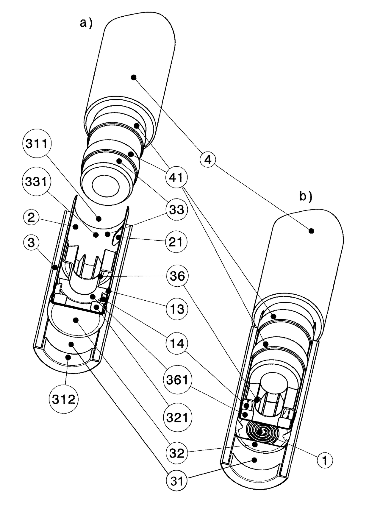
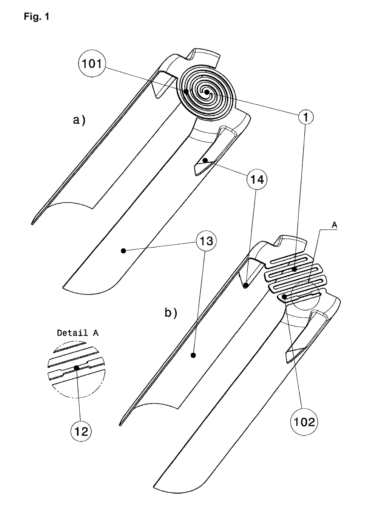
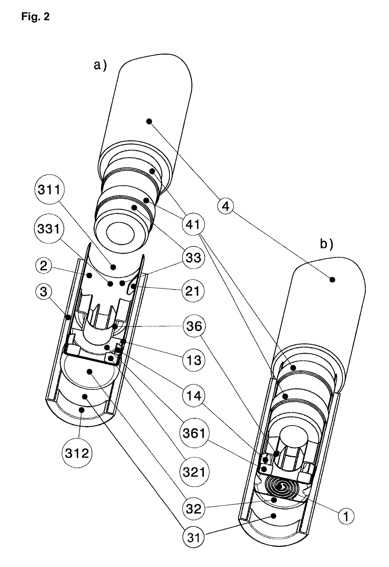
[0059]According to a preferred embodiment of the invention a device according to the present invention is used as a thermal resistor 1, e.g. in a device described in WO2011 / 0099 20, i.e. a device according to the present invention is combined with a device in which a fluid flows through at least one vaporizer membrane 32 in a flow channel 31, wherein the at least one vaporizer membrane 32 has been and / or is wetted with a substance containing active and / or aroma materials to be vaporized, the device according to the present invention supplying thermal energy to the substance containing active and / or aroma materials, whereby this substance is vaporized and supplied to the fluid stream.

[0060]According to this embodiment, the device according to the present invention comprises[0061]a hollow cylinder 31 consisting of a plastic film, a paperboard and cover paper, said cover paper being wound around the outer surface of the paperboard and corresponding preferably to the so-called cork pape...


PUM


Abstract

A vaporizer device for vaporizing substances is provided, containing active and / or aroma materials, including a mouthpiece with a fluid inlet and a fluid outlet, and including: a heating device with a thermal resistor being a metallic foil or a thin sheet configured as a dual coil and / or sinuous line with two ends and dimensions of the cross-section of a cigarette or a small cigar, wherein the interspaces of the dual coil and / or sinuous line allow fluid flow therethrough, contact tabs are connected to respective opposed ends of the dual coil and / or sinuous line and are not in direct contact with one another, and at least one permeable and wettable vaporizer membrane in large-area contact with the thermal resistor, wherein the thermal resistor and the at least one vaporizer membrane are arranged orthogonally or at an angle to the direction of the fluids passing through the mouthpiece.

Description

CROSS REFERENCE TO RELATED APPLICATION[0001]This application is a national phase application based on PCT / EP2012 / 069135, filed on Sep. 27, 2012.TECHNICAL FIELD[0002]The present invention relates in general to a device for optimized smoke-free inhalation of nicotine and / or additives with electronic cigarettes.GENERAL INTRODUCTION[0003]When a conventional cigarette is smoked, tobacco is burned and the smoke arising during this combustion is inhaled (mainstream smoke) or discharged into the surrounding environment (sidestream smoke).[0004]Mainstream smoke is the crucial factor in damaging the health of the consumer, but is what gives him / her the desired pleasure. Sidestream smoke is the crucial factor in damaging the health of passive smokers and is desired neither by the passive smokers nor by the consumer.[0005]Over 4800 different substances have been identified in cigarette smoke, of which around 70 are demonstrably carcinogenic.[0006]The aim of methods and devices based thereon for...

Claims


Application Information

Patent Timeline
Patent Type & Authority Patents(United States)
IPC IPC(8): A24F47/00H05B3/26A24F40/10A24F40/46A24F40/485A24F40/50
CPCA24F47/008H05B3/26H05B2203/013A24F40/46A24F40/10A24F40/50A24F40/485
Inventor RINKER, ARNOLITZENBERGER, PHILIPP
Owner PHILIP MORRIS PROD SA
Why Eureka
Try Eureka