System and method for maximizing short-term energy storage in a supercapacitor array for engine start applications

a supercapacitor array and short-term energy storage technology, which is applied in the direction of engine starters, machine/engines, electric generator control, etc., can solve the problems of low starting current, low starting current, and low efficiency of the supercapacitor array, so as to achieve a higher start-up voltage

Active Publication Date: 2017-11-14
EATON INTELLIGENT POWER LIMITED
View PDF24 Cites 12 Cited by
  • Summary
  • Abstract
  • Description
  • Claims
  • Application Information

AI Technical Summary

Benefits of technology

[0008]In accordance with another aspect of the present invention, a charger is provided for charging an arrangement of supercapacitor cells in a starting system for an internal combustion engine with a starter that runs from a battery system that is recharged from the internal combustion engine when running. The charger includes a DC-DC converter configured to convert a DC battery power received from a DC battery to a DC charging current for output to the arrangement of supercapacitor cells, a control module operably connected to the DC-DC converter to control operation of the DC-DC converter for outputting the DC charging current, and a bump-up command module operably connected to the control module to selectively transmit a bump-up command thereto. The control module is programmed to receive a bump-up command from the bump-up command module and, responsive to receiving the bump-up command, cause the DC-DC converter to output DC charging current to the arrangement of supercapacitor cells to temporarily increase a voltage of the arrangement of supercapacitor cells to a higher start-up voltage.

Problems solved by technology

When the battery is discharged to a level below that of a threshold start voltage, the battery, by itself, cannot supply an adequate current to the starter motor at the time of starting the engine.
While the above described technique for charging the supercapacitor array—with the voltage / potential of the cells of the supercapacitor array being held at a useful level but less than their max rated voltage when the cells are above 0° C. and being increased (e.g., to their max rated voltage) when the temperature of the cells drops below 0° C.—is effective with regard to providing a needed voltage boost during cold weather hard starting of the engine, it is recognized that this technique may not be ideal for maximizing energy extraction from the supercapacitor array.
First, because during warm conditions the technique holds the supercapacitor array at a relatively constant voltage indefinitely, that voltage and corresponding stored charge must be reduced to support long life of the cells—providing continuous higher voltage during warm conditions is not an option.
Second, as the charger is shut down during cold temperatures upon bringing the supercapacitor array up to its max rated voltage, the self discharge (leakage) currents of the cells and other parasitic loads over the following hours after charging may slowly discharge the supercapacitor array until it hits a lower threshold, at which point the charger turns back on and refreshes the lost charge and again cycles off.
Accordingly, if a given design implements 1 V or even just 0.5 V of charge hysteresis, a user cannot be assured when attempting to start a cold truck whether the expected max rated voltage boost is available for the starter or whether instead some lower voltage down to the refresh threshold is only available.
As set forth above, existing techniques for selectively holding and increasing the voltage / potential of the cells of the supercapacitor array are effective with regard to selectively providing a needed voltage boost during some occurrences of hard starting of the engine, but are not ideal for maximizing energy extraction from the supercapacitor array.

Method used


Image

  • System and method for maximizing short-term energy storage in a supercapacitor array for engine start applications
  • System and method for maximizing short-term energy storage in a supercapacitor array for engine start applications
  • System and method for maximizing short-term energy storage in a supercapacitor array for engine start applications

Examples


Embodiment Construction

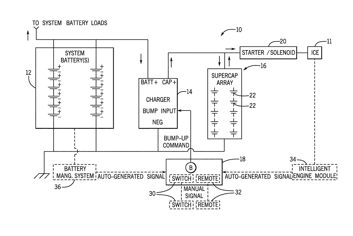
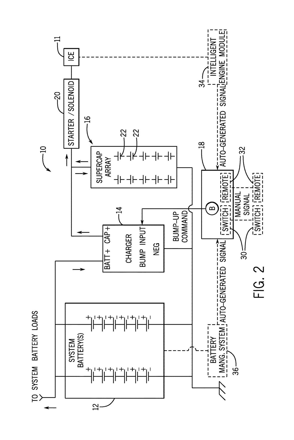
[0018]Embodiments of the invention are directed to a supercapacitor array and charger-implemented method of charging thereof in a controlled manner to maximize energy extraction and array lifetime. A charger included as part of a system for starting an internal combustion engine of a motor vehicle is programmed to temporarily bump-up a voltage of the supercapacitor array in an on-demand fashion, so as to maximize a voltage available from the supercapacitor array when starting the engine without significantly impacting the operational lifetime of the supercapacitor array.

[0019]Embodiments of the invention are described below as being directed to a system for starting an internal combustion engine in construction, agriculture, heavy trucking, and other specialty vehicles—with such vehicles including, for example, asphalt pavers, large tractors, road graders, field harvesters, and so forth. However, it is recognized that the charger and method performed thereby for charging the superca...


PUM


Abstract

A system for starting an internal combustion engine includes a battery system, a charger to receive DC battery power from the battery system and convert the power to a DC charging current, a supercapacitor array having a plurality of supercapacitor cells connected to the charger to receive the DC charging current therefrom, and a motor starter to start the internal combustion engine responsive to a DC input from the supercapacitor array. The charger modifies a voltage of the supercapacitor cells in an on-demand fashion, with the charger programmed to provide DC charging current to the supercapacitor array to hold the supercapacitor cells at a first voltage, receive a bump-up command indicative of an upcoming engine start and, responsive to receiving the bump-up command, provide DC charging current to the supercapacitor array to increase a voltage of the supercapacitor cells temporarily to a second voltage higher than the first voltage.

Description

BACKGROUND OF THE INVENTION[0001]Embodiments of the invention relate generally to an energy storage device used in an engine starting application and, more particularly, to a supercapacitor array and method of charging thereof in a controlled manner to maximize energy extraction and array lifetime.[0002]Motor vehicles typically utilize a starter motor for starting the vehicle's engine. The starter motor is supplied with electrical energy from a battery, such as a lead-acid storage battery. The battery is typically charged by an alternator while the motor vehicle is running. When the battery is discharged to a level below that of a threshold start voltage, the battery, by itself, cannot supply an adequate current to the starter motor at the time of starting the engine.[0003]With specific regard to heavy trucking applications, it has been previously recognized that double insulated capacitors—i.e., supercapacitors—are beneficial to supplement and indeed replace lead-acid batteries in ...

Claims


Application Information

Patent Timeline
Patent Type & Authority Patents(United States)
IPC IPC(8): F02N11/00H02J7/00H02P9/04F02N11/08H02J7/34
CPCF02N11/0866H02J7/0054H02J7/345F02N11/087F02N2011/0885F02N2011/0888F02N2200/023H02J7/342H02J2310/46
Inventor BUCHANAN, MARLOWE JAMES
Owner EATON INTELLIGENT POWER LIMITED
Why Eureka
Try Eureka