Supercharge Your Innovation With Domain-Expert AI Agents!

Modular RF matrix switch

a rf matrix switch and module technology, applied in the direction of waveguide type devices, gated amplifiers, support structure mounting, etc., can solve the problems of increasing system cost and size, affecting the effect of rf matrix switches, and multiple problems,

Active Publication Date: 2017-11-14
QUINTECH ELECTRONICS & COMM
View PDF18 Cites 0 Cited by
  • Summary
  • Abstract
  • Description
  • Claims
  • Application Information

AI Technical Summary

Benefits of technology

This approach significantly reduces power usage by up to 50% and decreases the need for cooling, while enabling cost-effective and flexible configuration of matrix sizes without altering the backplane or basic chassis configuration.

Problems solved by technology

However, large RF matrix switches have multiple issues.
A single “one size fits all” system size which might be cost effective for a fully populated matrix may not be cost effective for an application with fewer than the maximum inputs and outputs.
This quickly increases system cost and size.
Large RF matrix switches have high power consumption, along with heat generation and noise pollution from the high-speed fans required to cool the unit.
However, the Clos architecture is relatively inefficient and more expensive for less than fully populated configurations.
Because it is common in many applications to have more outputs than inputs, a standard three stage square or symmetrical matrix will be a costly solution for many of these cases.
However, because of the relatively low volume of RF matrix switches it is not cost effective to build different chassis configurations specifically for different application sizes.
Unfortunately Class A operation requires the most power of the amplifier bias classes.
For a large matrix module such as a 128×128 module, the power needed for amplifiers, the heat produced, and the cooling required become significant design and operation issues.
In the 3-stage Clos network in particular there are multiple paths available for any input to output connection, raising the probability of unused RF paths.
They remain on because turning off an amplifier that is not being used can adversely affect the RF signal traveling through other amplifiers and paths in the switch.
Keeping all amplifiers on all of the time produces high power consumption, along with associated heat generation and noise pollution from the high-speed fans required to cool the unit.

Method used


Image

  • Modular RF matrix switch
  • Modular RF matrix switch
  • Modular RF matrix switch

Examples


Embodiment Construction

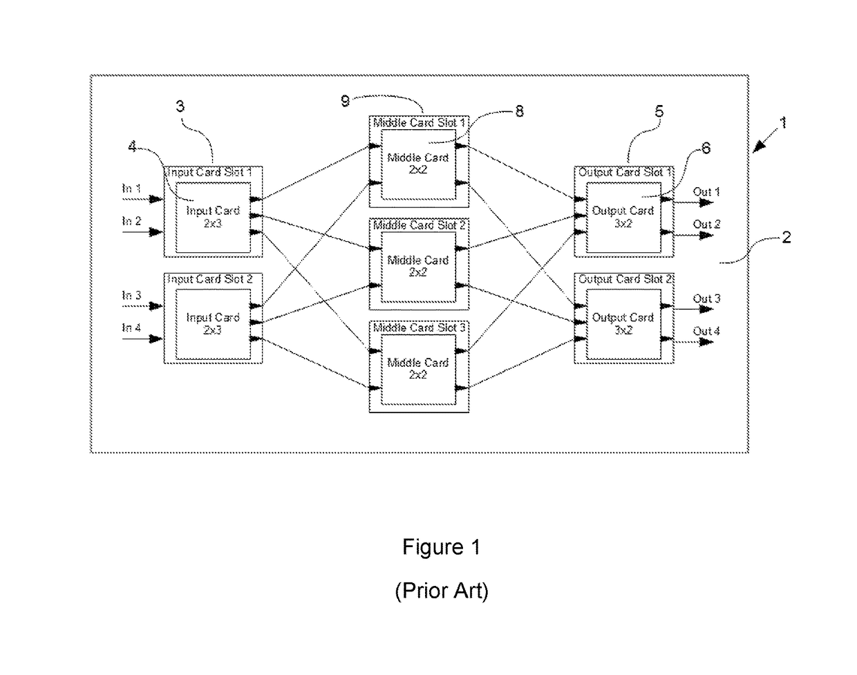
[0024]In an RF matrix switch there is a chassis which has a first set of card slots for input cards having input ports and a second set of card slots for output cards having output ports. The number of available input ports is usually the same as the number of available output ports. An example of a conventional three-stage 4×4 RF matrix switch is shown in FIG. 1. That RF matrix switch 1 has a chassis 2 having a first set of card slots 3 identified as input card slots in the drawing, each slot containing an input card 4. There is a second set of card slots 5 identified as output card slots in the drawing, each slot containing an output card 6. The first set of card slots 3 is usually in a different location on the chassis than the second set of card slots 5, such as on opposite sides or on opposite ends of the chassis. In the conventional RF matrix switch the input cards, and input slots are configured differently from the output cards and the output card slots such that the input c...


PUM


Abstract

An RF matrix switch has a first set of card slots at selected locations on the chassis and a second set of card slots at different selected locations on the chassis as well as input cards and output cards. The input cards, the output cards, the first set of card slots and the second set of card slots are all configured so that the input cards and the output cards fit into all of these slots. Reroute cards can be provided for any unused card slots. The RF matrix switch also may have an active power management system in which there is a power control switch connected to each amplifier that turns the amplifier off when the amplifier is not being used.

Description

CROSS-REFERENCE TO RELATED APPLICATION[0001]The present application claims priority to U.S. Provisional Application Ser. No. 62 / 044,522 which was filed on Sep. 2, 2014. The entirety of the Provisional Application is incorporated by reference herein.FIELD OF INVENTION[0002]The present invention relates to RF matrix switches which are commonly used in the telecommunications industry to connect RF signal sources to their destination.BACKGROUND OF THE INVENTION[0003]RF matrix switches are commonly used in telecommunications, typically in satellite downlink and uplink applications. They are used as physical layer switches to connect RF signal sources to their destinations. The incorporation of RF splitter or combiner circuits allows one signal source to be routed to multiple destinations or multiple signal sources to be routed to a single destination. Being able to make these connections on demand provides a great deal of flexibility in RF signal management and routing systems.[0004]One ...

Claims


Application Information

Patent Timeline
Patent Type & Authority Patents(United States)
IPC IPC(8): H05K7/14H03F3/19H03F3/21H03F1/02H03F3/72H05K1/14H01P1/10
CPCH03F3/211H03F1/0277H03F3/19H03F3/72H03F2203/7233H03F2200/451H03F2203/21139H04B1/00H04Q1/00H04Q3/00
Inventor PHELPS, THOMAS B.JOHNSTON, NICHOLAS J.
Owner QUINTECH ELECTRONICS & COMM
Features
  • R&D
  • Intellectual Property
  • Life Sciences
  • Materials
  • Tech Scout
  • Unparalleled Data Quality
  • Higher Quality Content
  • 60% Fewer Hallucinations
Learn More