Gas turbine with honeycomb seal

a technology of honeycomb seal and turbine blade, which is applied in the field of gas turbines, can solve the problems of economic efficiency, durability, and inability to solve the technology, and achieve the effect of improving the abrasion resistance of the honeycomb seal by the turbine blade and the seal fin

Active Publication Date: 2017-11-21
MITSUBISHI POWER LTD
View PDF32 Cites 5 Cited by
  • Summary
  • Abstract
  • Description
  • Claims
  • Application Information

AI Technical Summary

Benefits of technology

[0017]The present invention has been made in view of the above problem and aims to provide a gas turbine that can solve the problem in which a seal fin of a turbine blade is abraded by the brazed places of a honeycomb seal.
[0019]The gas turbine according to the present invention is such that the longer direction of the wall of node of the corrugated thin sheet metal forming the honeycomb seal, that is, the longer direction of the brazed place whereby the walls of node are secured to each other is tilted with respect to the rotational direction of the turbine blade. The abradability of the honeycomb seal by the turbine blade and the seal fin can be improved and the abrasion of the seal fin by the honeycomb seal can be suppressed accordingly.

Problems solved by technology

However, these conventional technologies require a honeycomb seal having a special shape and material and have problems in terms of economic efficiency, abradability, and durability.
The technology fails to solve the above-described problem in which the seal fin of the turbine blade is abraded by the brazed places of the honeycomb seal.

Method used


Image

  • Gas turbine with honeycomb seal
  • Gas turbine with honeycomb seal
  • Gas turbine with honeycomb seal

Examples


first embodiment

Honeycomb Seal and its Securing Structure

[0041]FIG. 3 is a schematic view illustrating a honeycomb seal and explains a first relation between the honeycomb seal and the rotational direction of a turbine blade (a honeycomb seal securing structure according to a first embodiment)

[0042]The honeycomb seal 7 has a hexagonal honeycomb structure configured in the following manner. Corrugated thin sheet metals 71 are each formed such that trapezoidal concavities and convexities are alternately continued. A plurality of the corrugated thin sheet metals 71 are joined to each other. Honeycomb shapes including approximately hexagonal voids and walls of node are continued to provide the hexagonal honeycomb structure. The hexagonal honeycomb structure is brazed to the shroud 2.

[0043]To manufacture the honeycomb seal 7, a thin sheet material is pressed to form a corrugated thin sheet metal 71. The corrugated thin sheet metals 71 are joined to each other through welding, brazing, or other methods t...

second embodiment

Honeycomb Seal Securing Structure

[0050]FIG. 4 is a view for explaining a second relation between a honeycomb seal and the rotational direction of a turbine blade (a honeycomb seal securing structure according to a second embodiment).

[0051]The arrangement formation of the honeycomb seal illustrated in FIG. 4 is such that a setting angle θ between the longer direction (the Y1 direction) of the wall of node 71a and the rotational direction (the Z direction) of the turbine blades 5A-5C is set at a range from 30 degrees to less than 90 degrees.

[0052]A length in which the walls of node 71a and the brazed place 72 are abraded by the seal fin 6 is greater than that in the case where the setting angle θ is 90 degrees. However, the study of the present inventors shows that if the setting angle θ is within a range equal to or greater than 30 degrees, an effect of preventing the breakage of the seal fin 6 can sufficiently be attained.

third embodiment

Honeycomb Seal Securing Structure

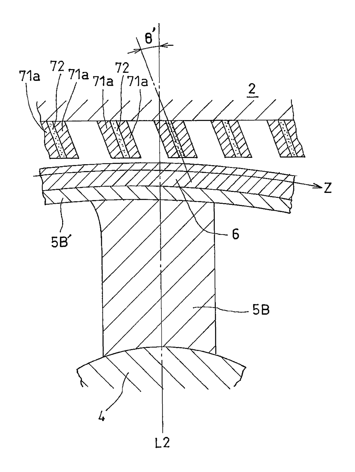
[0053]FIG. 5 is a view for explaining a honeycomb seal securing structure according to a third embodiment.

[0054]The securing structure of the honeycomb seal illustrated in FIG. 5 is as follows: for example, as illustrated in FIGS. 3 and 4, a setting angle θ between the longer direction (the Y1 direction) of the wall of node 71a and the rotational direction (the Z direction) of the turbine blades 5A-5C is set at a range from 30 to 90 degrees. In addition to this securing structure of the honeycomb seal 7, the wall of node 71a and the brazed place 72 are tilted at a tilt angle θ′ in a range between 15 degrees and 45 degrees in the rotational direction (the Z direction) of the turbine blade with respect to a vertical axis L2 perpendicular to the rotating shaft 4.

[0055]The study of the present inventors shows that since the honeycomb seal 7 has the tilt angle tilted in the rotational direction of the turbine blade in such an angle range, a load received ...


PUM


Abstract

A gas turbine includes a compressor, a combustor, and a turbine. The turbine includes a honeycomb seal disposed so as to be secured to a casing side in a clearance between the casing and turbine blades rotating around a rotating shaft and a seal fin that is provided on an end face of each of the turbine blades facing the honeycomb seal. The seal fin extends in a direction perpendicular to the rotating shaft. The honeycomb seal is formed by a plurality of corrugated sheet metals overlapped with each other at walls of nodes thereof and the walls of the nodes are blazed with each other. Each of the corrugated sheet metals has trapezoids formed in alternating fashion. A longer direction of each wall of the nodes of the honeycomb seal is angled with respect to the rotational direction of the turbine blades.

Description

BACKGROUND OF THE INVENTION[0001]1. Field of the Invention[0002]The present invention relates to a gas turbine that is provided with an abradable honeycomb seal installed to reduce the leakage of working fluid from a clearance between turbine blades and a casing.[0003]2. Description of the Related Art[0004]In a gas turbine mainly including a compressor, a combustor, and a turbine, high-temperature combustion gas flows between turbine blades installed on a rotating shaft and stator vanes installed on a stationary casing side. It is desirable to prevent the combustion gas from leaking from the turbine blade tip clearance in terms of the performance of the turbine. To meet such request, a gas turbine provided with an abradable honeycomb seal secured to the casing side is generally used. This honeycomb seal is manufactured in the following manner: a thin sheet metal is processed to form a corrugated shape in which trapezoids are alternately continued; a plurality of the corrugated thin ...

Claims


Application Information

Patent Timeline
Patent Type & Authority Patents(United States)
IPC IPC(8): F01D11/12
CPCF01D11/127F05D2250/283
Inventor ARIKAWA, HIDEYUKIKASUYA, TADASHIKOJIMA, YOSHITAKAWATANABE, YASUYUKIMURAKATA, TADASHIICHIKAWA, KUNIHIROKONRAI, TAKUMI
Owner MITSUBISHI POWER LTD
Why Eureka
Try Eureka