Waveguide polarizing optical device

a waveguide and optical device technology, applied in the direction of polarizing elements, optical fibres with polarisation, instruments, etc., can solve the problems of very sensitive curvature curvature curvature drawbacks of polarizing fibers, and achieve the effect of better polarization rejection ratio of at least one thin-plate polarizer

Active Publication Date: 2017-11-21
EXAIL
View PDF7 Cites 0 Cited by
  • Summary
  • Abstract
  • Description
  • Claims
  • Application Information

AI Technical Summary

Benefits of technology

[0030]This combination of two particular polarizers in series allows increasing the polarization rejection ratio by comparison with a polarizing device of the prior art including only one waveguide polarizer on an integrated optical circuit, without generating spurious interference effects. Moreover, this combination induces extremely limited insertion losses and does not modify the bulkiness of the integrated optical circuit.
[0051]Advantageously, the polarization rejection ratio of the at least one thin-plate polarizer is better than −20 dB and, preferably, the polarization rejection ratio of the waveguide polarizer is better than −40 dB.

Problems solved by technology

However, a polarizing fiber has for drawback to be very sensitive to the curvatures: the losses and the polarization extinction ratio (PER) are modified as a function of the radius of curvature and of the axis of such a curvature.

Method used


Image

  • Waveguide polarizing optical device
  • Waveguide polarizing optical device
  • Waveguide polarizing optical device

Examples


first embodiment

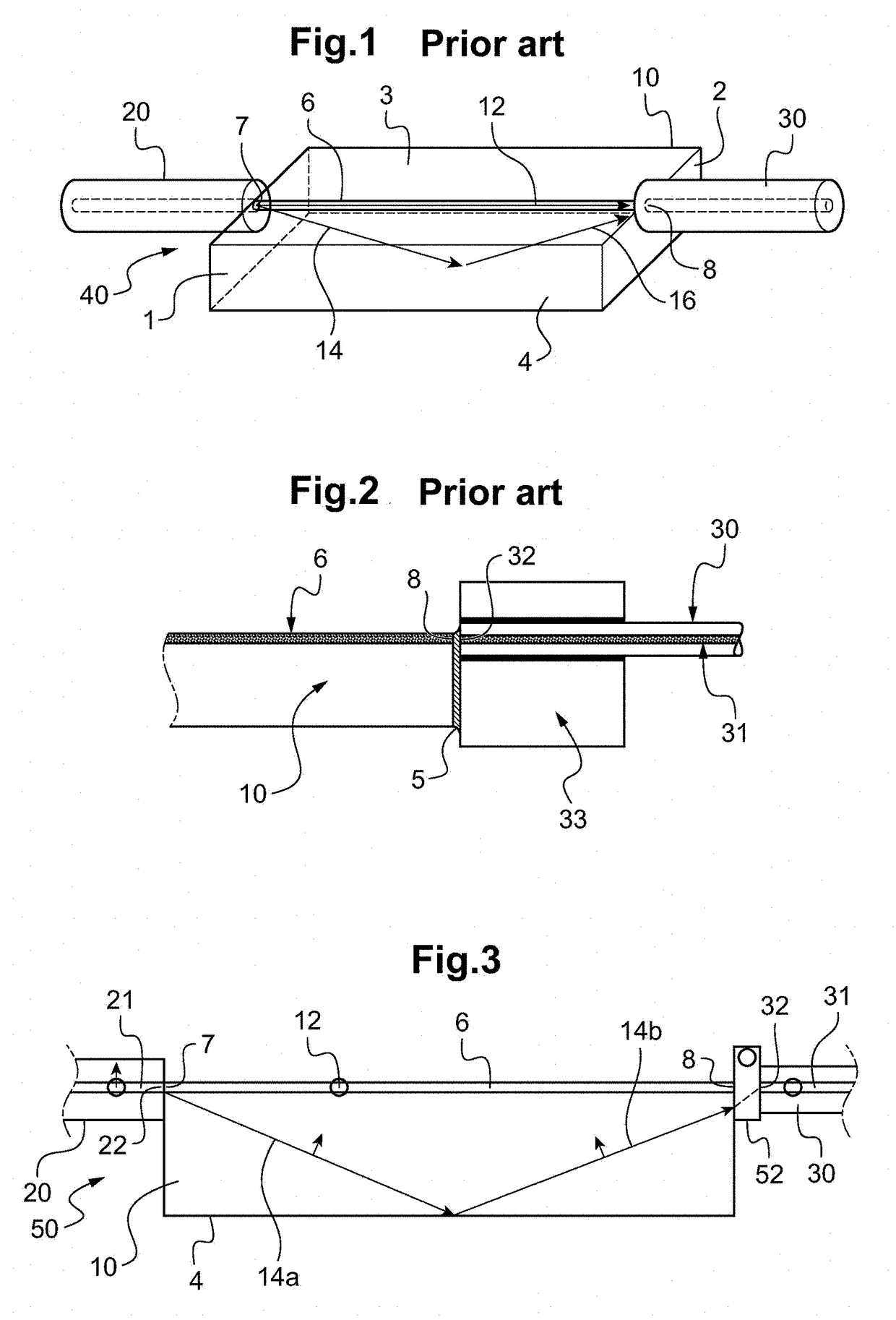
[0064]FIG. 3 schematically shows a sectional view of a polarizing optical device according to the invention;

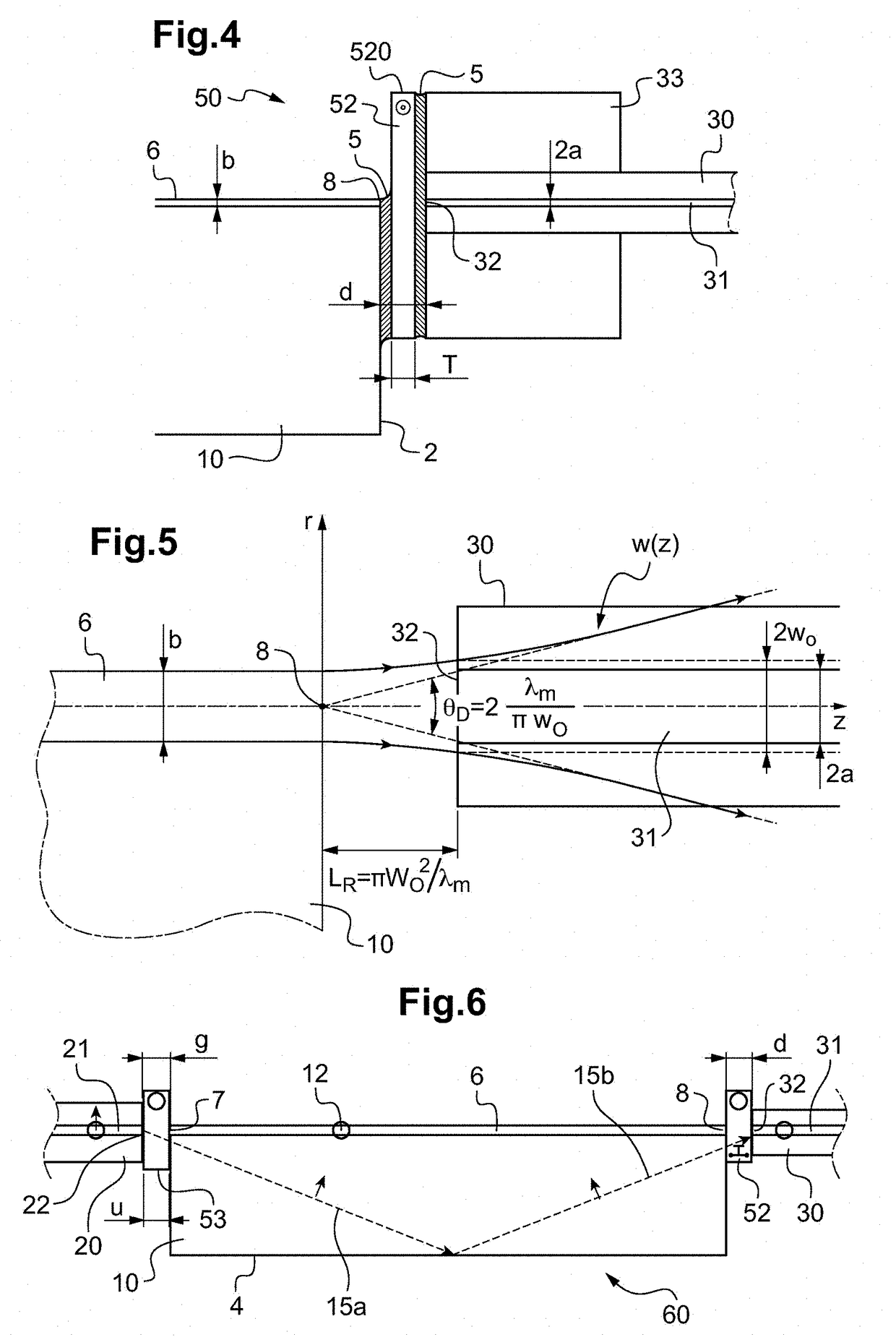
[0065]FIG. 4 schematically shows a sectional view of a detail of a polarizing optical device according to an embodiment of the invention;

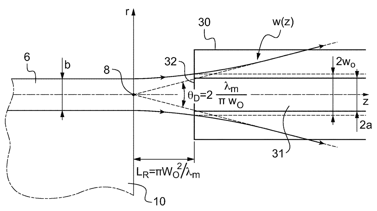
[0066]FIG. 5 illustrates the divergence of a Gaussian beam at the output of a single-mode optical fiber;

second embodiment

[0067]FIG. 6 schematically shows a sectional view of a polarizing optical device according to the invention.

DEVICES

[0068]FIG. 3 proposes a polarizing optical device 50 comprising a first optical waveguide 20, a first waveguide polarizer 6, a second polarizer 52 and a second optical waveguide 30. The polarizing device 50 hence comprises a mounting of at least two polarizers in series in a particular configuration that allows attenuating the propagation of non-guided spurious beams without inducing noticeable losses.

[0069]A first waveguide polarizer 6 is chosen. Preferably, the first polarizer 6 is a waveguide polarizer integrated on the substrate 10 of an integrated optical circuit. Preferably, the first polarizer 6 is formed by proton exchange on a lithium niobate substrate. In another variant, the first polarizer 6 is a polarizing fiber.

[0070]An aspect of the invention consists in selecting a second polarizer 52 operating in transmission and having an ultra-thin thickness. Preferab...


PUM


Abstract

Disclosed is a waveguide polarizing optical device, including a first waveguide polarizer (6), a section of a second optical waveguide (31) and a second thin-plate polarizer (52) having a physical thickness T and a refractive index n, the second thin-plate polarizer (52) being disposed on the optical path between a waveguide end (8) of the first polarizer (6) and one end (32) of the second optical waveguide (31), the physical distance d between the waveguide end (8) of the first polarizer (6) and the end (32) of the second optical waveguide (31) being less than or equal to twice the Rayleigh length and the physical thickness T of the second polarizer (52) being less than or equal to the physical distance d.

Description

TECHNICAL FIELD TO WHICH THE INVENTION RELATES[0001]The present invention relates to a polarizing optical device.[0002]More precisely, the invention relates to a waveguide polarizing optical device comprising an integrated optical circuit (IOC).TECHNOLOGICAL BACKGROUND[0003]Many integrated optical circuits exist, consisted of a planar substrate and an optical waveguide deposited on the planar substrate. The IOCs are generally manufactured by techniques of microlithography and / or thermal diffusion. The integrated optical circuits may be manufactured from substrates of different materials such as semiconductors, glass or lithium niobate (LiNbO3) or lithium tantalate (LiTaO3). There exist different optical components on integrated optical circuit: polarizer, phase modulator, Mach-Zehnder interferometer, Y-junction, 2×2 coupler or 3×3 coupler. Especially, the integrated optical circuits formed by proton exchange on lithium niobate find many applications, for example in rotation measurem...

Claims


Application Information

Patent Timeline
Patent Type & Authority Patents(United States)
IPC IPC(8): G02B6/27G02B6/126G02B5/30G02B6/30G02B6/024
CPCG02B6/2706G02B5/3033G02B6/024G02B6/30G02B6/2726G02B6/2766G02B6/126G01D5/35322
Inventor SIMONPIETRI, PASCALCHOUVIN, STEPHANEMOLUCON, CEDRIC
Owner EXAIL
Why Eureka
Try Eureka