Systems and methods to reduce fluid contamination

a technology of fluid contamination and system, applied in the field of systems and methods to reduce fluid contamination, can solve the problems of contamination of withdrawn blood, known systems for analyte monitoring in a hospital or clinical setting may suffer from various drawbacks, and jeopardize the health of a patient, so as to improve the measurement accuracy of analyte monitoring system, and reduce the risk of contamination in drawing fluid

Inactive Publication Date: 2017-12-26
OPTISCAN BIOMEDICAL
View PDF21 Cites 4 Cited by
  • Summary
  • Abstract
  • Description
  • Claims
  • Application Information

AI Technical Summary

Benefits of technology

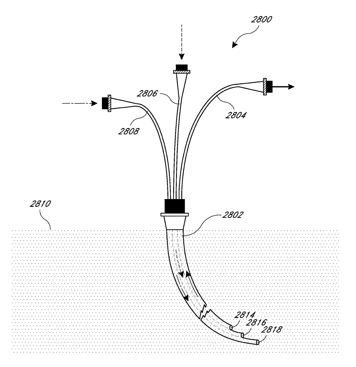
[0008]In various embodiments, a system for reducing contamination risk in drawing fluid from vasculature is described. The system comprises a tube configured to connect to a multi-lumen catheter. In various embodiments, the multi-lumen catheter can include a proximal port comprising an independent lumen that provides a fluid path between an extracorporeal opening and an intravascular opening that is positioned upstream when the multi-lumen catheter is inside a vessel having a fluid flow; a distal port comprising an independent lumen that provides a fluid path between the extracorporeal opening and the intravascular opening that is positioned downstream from the proximal port when the multi-lumen catheter is inside a vessel having a fluid flow; and a medial port comprising an independent lumen that provides a fluid path between the extracorporeal opening and the intravascular opening that is positioned between the proximal port and the distal port. In various embodiments, the distal and medial ports can each be configured to allow infusion of an infusate into the vessel from their intravascular openings downstream from the intravascular opening of the proximal port. In various embodiments, the tube can be configured to connect to the proximal port of the multi-lumen catheter without leaking. In various embodiments, the tube can have an inner lumen that is smaller than the inner lumen of the independent lumen of the proximal port. For example, the diameter of the inner lumen of the tube can be between approximately 0.01 inches and 0.04 inches. The system further comprises a fluid pressure system in fluid communication with the inner lumen of the tube that can be configured to create a pressure in the inner lumen that is automatically controlled to be less than 10 psi and / or provide a flow rate of between approximately 1 and 10 ml per minute such that the amount of contaminating infusate that is drawn into the intravascular opening of the proximal port is limited to less than 10 parts per million. The fluid pressure system may be configured to create a negative pressure in the inner lumen that is between approximately 40% and approximately 99% of the pressure in the vessel. The fluid pressure system may comprise a syringe pump.
[0009]A method for reducing contamination risk in drawing fluid from vasculature is described. The method comprises providing a tube that is configured to connect to a multi-lumen catheter. In various embodiments, the multi-lumen catheter can have a proximal port comprising an independent lumen that provides a fluid path between an extracorporeal opening and an intravascular opening that is positioned upstream when the multi-lumen catheter is inside a vessel having a fluid flow; a distal port comprising an independent lumen that provides a fluid path between the extracorporeal opening and the intravascular opening that is positioned downstream from the proximal port when the multi-lumen catheter is inside a vessel having a fluid flow; and a medial port comprising an independent lumen that provides a fluid path between the extracorporeal opening and the intravascular opening that is positioned between the proximal port and the distal port. In various embodiments, the distal and medial ports can each be configured to allow infusion of an infusate into the vessel from their intravascular openings downstream from the intravascular opening of the proximal port. In various embodiments, the tube can be configured to connect to the proximal port of the multi-lumen catheter without leaking. In various embodiments, the tube can have an inner lumen that is smaller than the inner lumen of the independent lumen of the proximal port. For example, the diameter of the inner lumen of the tube can be between approximately 0.01 inches and 0.04 inches. The method further comprises providing a fluid pressure system in fluid communication with the inner lumen of the tube and providing an automated system that is configured to automatically control the fluid pressure system and create a pressure in the inner lumen that is less than 10 psi and / or provide a flow rate of between approximately 1 and 10 ml per minute such that the amount of contaminating infusate that is drawn into the intravascular opening of the proximal port is limited to less than 10 parts per million. The automated system may control the fluid pressure system to create a negative pressure in the inner lumen that is between approximately 40% and approximately 99% of the pressure in the vessel. The fluid pressure system may comprise a syringe pump.
[0010]An apparatus for improving measurement accuracy in an analyte monitoring system and reducing fluid contamination risk is described. The apparatus may include a fluid passage with a tip configured to mate with a multi-lumen catheter without leaking. The multi-lumen catheter may have a proximal port communicating with a proximal port lumen that provides a fluid path to a proximal intravascular opening that is configured to open into a vessel having a fluid flow and a distal port communicating with a distal port lumen that is independent from and not in fluid communication with the proximal port lumen and that provides a fluid path to a distal intravascular opening that is configured to open into the vessel distal of and downstream from the proximal intravascular opening to infuse infusates. The apparatus may include a fluid pressure system in fluid communication with the fluid passage, the fluid pressure system configured to periodically automatically draw fluid from the vessel through the proximal intravascular opening and the proximal port and through the tip back into the fluid passage while maintaining a low pressure and / or flow rate to thereby reduce risk of reversing the fluid flow in the vessel and drawing infusates back upstream into the proximal intravascular opening. The apparatus may also have an analyzer configured to automatically analyze at least a portion of the drawn fluid, automatically achieving higher accuracy analysis at least in part as a result of the low pressure at which the fluid was drawn. The apparatus may be configured to reduce dilution errors due to withdrawal of infusates such that infusate does not cause more than a 20% difference in accuracy of an analyte reading that uses fluid drawn into the intravascular opening of the proximal port. The fluid passage may have an inner diameter of between approximately 0.01 inches and approximately 0.04 inches. The fluid pressure system may comprise a controller and a pressure monitor that provides feedback to the controller, the controller configured to maintain the withdrawal pressure below 99% of the pressure of blood in the vessel. A patient blood pressure monitor may provide feedback to the controller to allow a baseline for comparison to the withdrawal pressure. The pressure monitor may be configured to monitor the pressure at or near the proximal port. The fluid pressure system may be configured to maintain a constant rate for the majority of the time blood is being withdrawn through the proximal port. The fluid pressure system may be configured to adjust the withdrawal rate to be lower when infusates are being infused through the distal port
[0011]A method for improving measurement accuracy in an analyte monitoring system and reducing fluid contamination risk is described. The method may comprise providing a tube configured to connect to a multi-lumen catheter without leaking, the multi-lumen catheter having an upstream port and a downstream port, each port having an independent lumen not in fluid communication with the other. The method may further comprise positioning the multi-lumen catheter in a patient's vessel such that the lumen of the upstream port opens into the vessel upstream of the lumen of the downstream port, providing an automated fluid pressure system configured to automatically maintain a low pressure and / or flow rate while drawing blood, connecting the automated fluid pressure system to the tube such that the system is in fluid communication with the upstream port and blood flow in the patient's vessel, and using the automated fluid pressure system to periodically draw blood in through the lumen of the upstream port while maintaining a low pressure and / or flow rate, thereby avoiding a reversal of blood flow in the patient's vessel and reducing the risk of contamination of a blood sample. The infusate may be infused into the vessel through the downstream port, and the method further comprising reducing the amount of infusate drawn into the lumen of the upstream catheter so that infusate does not cause more than a 20% difference in accuracy of an analyte reading of the blood drawn into the tube as compared to a reading of blood drawn when no infusate is being infused into the vessel. The automated fluid pressure system may comprise a syringe pump. The infusate may be periodically infused into the vessel through the downstream port, the method further comprising using the automated fluid pressure system to reduce the pressure and / or flow rate of withdrawn blood when infusion of infusate and blood withdrawal occur simultaneously. The method may also include determining the patient's blood pressure and using the automated fluid pressure system to maintain a withdrawal pressure that is less than the patient's blood pressure, thereby avoiding reversal of blood flow in the vessel.

Problems solved by technology

This can be done, for example, in a hospital or clinical setting when there is a risk that the levels of certain analytes may move outside a desired range, which in turn can jeopardize the health of a patient.
Currently known systems for analyte monitoring in a hospital or clinical setting may suffer from various drawbacks.
For example, present fluid withdrawal techniques can result in fluid (e.g. blood) being withdrawn at a fast rate and / or at high pressures which can lead to contamination of the withdrawn blood particularly in multi-lumen catheters, where fluids from the other ports of the multi-lumen catheter can contaminate the withdrawn blood.

Method used


Image

  • Systems and methods to reduce fluid contamination
  • Systems and methods to reduce fluid contamination
  • Systems and methods to reduce fluid contamination

Examples


example experiment 1

[0230]In this example experiment, a partial least squares (PLS) regression method was applied to the infrared target spectra of the target patients' blood plasma to obtain the glucose estimates. In example experiment 1, estimated glucose concentration was not corrected for effects of interferents. The Sample Population used for the analysis included infrared spectra and independently measured glucose concentrations for 92 individuals selected from the general population. This Sample Population will be referred to as a “Normal Population.”

example experiment 2

[0231]In example experiment 2, an embodiment of the Parameter-Free Interferent Rejection (PFIR) method was used to estimate glucose concentration for the same target population of patients in example experiment 1. The Sample Population was the Normal Population. In this example, calibration for Library Interferents was applied to the measured target spectra. The Library of Interferents included spectra of the 59 substances listed below:

[0232]

Acetylsalicylic AcidHetastarchPyruvate SodiumAmpicillin SulbactamHuman AlbuminPyruvic AcidAzithromycinHydroxy Butyric AcidSalicylate SodiumAztreonamImipenem CilastatinSodium AcetateBacitracinIohexolSodium BicarbonateBenzyl AlcoholL_ArginineSodium ChlorideCalcium ChlorideLactate SodiumSodium CitrateCalcium GluconateMagnesium SulfateSodium ThiosulfateCefazolinMaltoseSulfadiazineCefoparazoneMannitolUreaCefotaxime SodiumMeropenemUric AcidCeftazidimeOxylate PotassiumVoriconazoleCeftriaxonePhenytoinXylitolD_SorbitolPhosphates PotassiumXyloseDextranPip...

example experiments 3 and 4

[0237]Example experiments 3 and 4 use the analysis methods of example experiments 1 and 2, respectively (PLS without interferent correction and PFIR with interferent correction). However, example experiments 3 and 4 use a Sample Population having blood plasma spectral characteristics different from the Normal Population used in example experiments 1 and 2. In example experiments 3 and 4, the Sample Population was modified to include spectra of both the Normal Population and spectra of an additional population of 55 ICU patients. These spectra will be referred to as the “Normal+Target Spectra.” In experiments 3 and 4, the ICU patients included Surgical ICU patients, Medical ICU patients as well as victims of severe trauma, including a large proportion of patients who had suffered major blood loss. Major blood loss may necessitate replacement of the patient's total blood volume multiple times during a single day and subsequent treatment of the patient via electrolyte and / or fluid repl...


PUM


Abstract

Methods and systems for determining the concentration of one or more analytes from a sample such as blood or plasma are described. The systems described herein can be configured to withdraw a certain volume of sample from a source of bodily fluid, direct a first portion of the withdrawn sample to an analyte monitoring system and return a second portion of the sample to the patient. The analyte monitoring system can include an automated blood withdrawal system that is configured to withdraw blood from the patient's vasculature at low pressure and / or withdrawal rates so as to reduce or prevent contamination of the withdrawn fluid from the infusion fluids.

Description

CROSS-REFERENCE TO RELATED APPLICATIONS[0001]This application claims the benefit under 35 U.S.C. §119(e) of U.S. Provisional Application No. 61 / 355,982, titled “Systems and Methods to Reduce Fluid Contamination,” filed on Jun. 17, 2010. The entire disclosure of the above-identified application is incorporated by reference herein and made part of this specification.[0002]This application also incorporates by reference herein and makes the entire disclosure of each of the following part of this specification: U.S. patent application Ser. No. 12 / 247,956, titled “Low Draw Volume Analyte Detection Systems,” filed on Oct. 8, 2008, which claims benefit under 35 U.S.C. §119(e) of U.S. Provisional Application No. 60 / 979,354, titled “Low Flush Volume Analyte Detection System,” filed on Oct. 11, 2007; and U.S. Provisional Patent Application No. 60 / 978,385, titled “Dilution Calibration For An Analyte Detection System,” filed on Oct. 8, 2007.BACKGROUND[0003]Field[0004]Some embodiments of the dis...

Claims


Application Information

Patent Timeline
Patent Type & Authority Patents(United States)
IPC IPC(8): A61B5/00A61D5/00B65D81/00B65D33/00A61M1/00A61M5/172A61M27/00A61B5/145A61B5/1459A61B5/1495A61B5/15A61B5/153A61B5/157A61M5/14A61M5/145A61M5/142
CPCA61B5/4839A61B5/1495A61B5/14532A61B5/15003A61B5/153A61B5/157A61B5/150221A61B5/150229A61B5/150236A61B5/150244A61B5/150389A61B5/150503A61B5/150755A61B5/150992A61B5/6866A61M5/1415A61M5/1723A61B5/1459A61M2230/201A61M5/1452A61M2005/14208A61M2205/3331A61M2205/50A61M2205/52
Inventor RULE, PETERBRAIG, JAMES R.KEENAN, RICHARDCALLICOAT, DAVID N.
Owner OPTISCAN BIOMEDICAL
Why Eureka
Try Eureka