Coupled-resonator on-die filters for WiFi applications

a technology of on-die filter and coupled resonance, which is applied in the direction of impedence networks, multiple-port networks, electrical apparatus, etc., can solve the problems of high level of unwanted emissions of counterpart receivers, interference of signals generated at 5 ghz power amplifiers with 2 ghz low noise amplifiers, and insufficient power generation of transceiver circuitry. it can achieve low insertion loss, improve matching characteristics, and high rejection rate

Active Publication Date: 2017-12-26
SKYWORKS SOLUTIONS INC
View PDF15 Cites 9 Cited by
  • Summary
  • Abstract
  • Description
  • Claims
  • Application Information

AI Technical Summary

Benefits of technology

[0014]The present disclosure is directed to filtering of unwanted emissions in dual band WLAN systems based on two coupled resonators. The filter is understood to have low insertion loss with improved matching characteristics. Different combinations of the resonator circuits may achieve high levels of rejection at particular frequencies of interest where local oscillator spurs and other unwanted signals are known to occur in 2 GHz and 5 GHz WLAN systems.

Problems solved by technology

In most cases, the transceiver circuitry itself does not generate sufficient power or have sufficient sensitivity necessary for communications.
During concurrent operation, the 5 GHz transceiver and related circuitry, and the 2 GHz transceiver and related circuitry, can generate high levels of unwanted emissions for counterpart receivers.
In the aforementioned WLAN system, whether dual antenna or single antenna, signals generated at the 5 GHz power amplifier can interfere with 2 GHz low noise amplifier.
Conversely, the signals generated at the 2 GHz power amplifier can interfere with the 5 GHz low noise amplifier.
Furthermore, there may be interference as between the two switches, the output ports of the front end circuit, and the antennas.
In such case, interference from and interference to these other modalities may also occur.
Indeed, if the transmit chain has sufficient gain, these spurious emissions may be amplified and transmitted such that government-mandated co-existence parameters are exceeded and would limit or prevent the operation of other wireless systems.
Even in unrestricted frequency bands, different locales may limit the level of allowed emissions.
However, such filters typically have high insertion loss on the order of 10 dB or greater, and the matching characteristics are problematic.

Method used


Image

  • Coupled-resonator on-die filters for WiFi applications
  • Coupled-resonator on-die filters for WiFi applications
  • Coupled-resonator on-die filters for WiFi applications

Examples


first embodiment

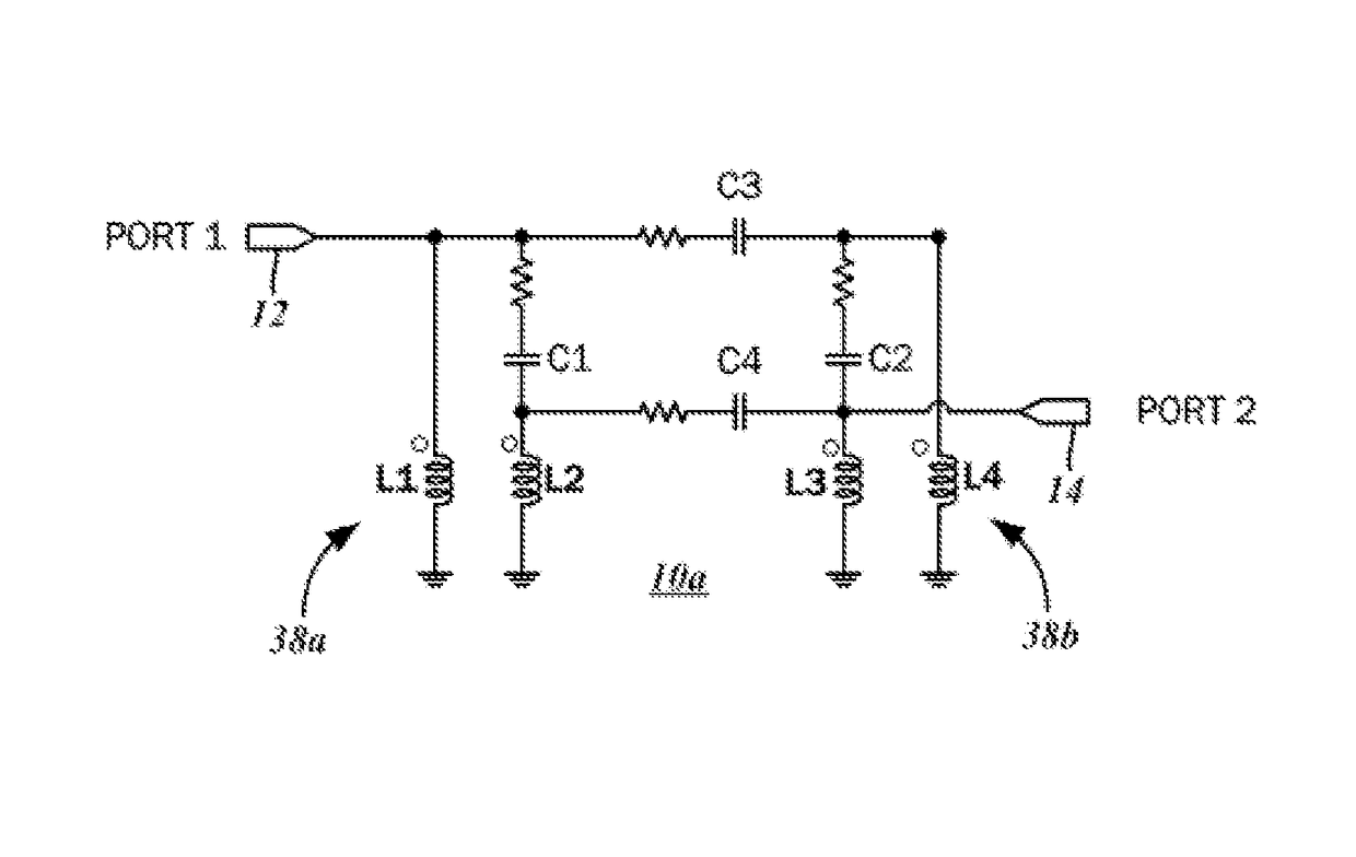
[0055]With reference to the schematic diagram of FIG. 1, a coupled resonator filter 10a generally has a first port 12 and a second port 14. The first port 12 is understood to be an input port, and accordingly receives an input signal. Various embodiments of the present disclosure contemplate the rejection of spurious emissions from a dual band, 2.4 GHz / 5 GHz WLAN transceiver, also referred to as WiFi, and so the input signal is understood to be that which is generated thereby. The coupled resonator filter 10 rejects these spurious emissions from the input signal, and passes the same to the second port 14, which is understood to be an output port. It is possible for the first port 12 to serve as the output port and for the second port 14 to serve as the input port, however.

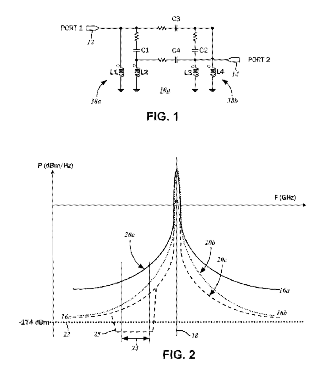
[0056]The graph of FIG. 2 illustrates one possible interference from WLAN transmit signals as affecting a GPS (Global Positioning System) receiver. A first plot 16a is of the WLAN transmit signal at the WLAN antenn...

second embodiment

[0068]The graph of FIG. 7 plots the various S-parameters of the coupled resonator filter 10b. A first plot 40a shows the input return loss S11, a second plot 40b shows the output return loss S22, a third plot 40c shows the gain S21 and a fourth plot 40d shows the isolation S12. As shown, the input return loss S11 and the output return loss S12 are both less than −15 dB at the 2.4 GHz WLAN operating frequency.

[0069]Referring now to the schematic diagram of FIG. 8, a third embodiment of the coupled resonator filter 10c is understood to be comprised of a first stage 42a and a second stage 42b, both of which are identically configured. As will be discussed below, there are variations in the way the first stage 42a and the second stage 42b are interconnected, with the first variant thereof being the third embodiment 10c. Both stages are comprised of the first resonator circuit 38a and the second resonator circuit 38b. As described above, the first resonator circuit 38a includes the capac...

third embodiment

[0071]This cascaded configuration is envisioned to yield a substantial enhancement in the rejection of spurious signal components in certain cellular communications operating frequencies—in particular, those below 2.17 GHz, as well as GPS receive frequencies in the 1.575 GHz range. It is possible for the rejection levels to exceed 50 dB. Similar input and output return loss performance is expected with respect to the coupled resonator filter 10c. The graph of FIG. 9 plots the various S-parameters therefor, and includes a first plot 40a showing the input return loss S11, a second plot 40b showing the output return loss S22, a third plot 40c showing the gain S21 and a fourth plot 40d showing the isolation S12.

[0072]The schematic diagram of FIG. 10 is of a fourth embodiment 10d of the coupled resonator filter, also referred to as a second variation of the cascaded configuration. Similar to the third embodiment 10c, there are two stages 42a, 42b, but as will be described in further deta...


PUM


Abstract

A radio frequency (RF) filter circuit for rejecting one or more spurious components of an input signal has a first resonator circuit including a first capacitor and a first coupled inductor pair of a first inductor and a second inductor, and a second resonator circuit with a second capacitor and a second coupled inductor pair of a third inductor and a fourth inductor. First and second resonator coupling capacitors are connected to the first resonator circuit and the second resonator circuit. A first port and a second port are connected to the first resonator circuit and the second resonator, with the filtered signal of the input signal passed through both the first resonator circuit and the second resonator circuit being output.

Description

CROSS-REFERENCE TO RELATED APPLICATIONS[0001]This application relates to and claims the benefit of U.S. Provisional Application No. 61 / 819,469, filed May 3, 2013 and entitled COUPLED RESONATOR ON DIE FILTERS FOR WIFI APPLICATIONS, the entirety of the disclosure of which is wholly incorporated by reference herein.STATEMENT RE: FEDERALLY SPONSORED RESEARCH / DEVELOPMENT[0002]Not ApplicableBACKGROUND[0003]1. Technical Field[0004]The present disclosure relates generally to radio frequency (RF) signal circuitry, and more particularly, to coupled resonator on-die filters for WiFi applications.[0005]2. Related Art[0006]Wireless communications systems are utilized in a variety contexts involving information transfer over long and short distances alike, and a wide range of modalities for addressing the particular needs of each being known in the art. As a general matter, wireless communications involve a radio frequency (RF) carrier signal that is variously modulated to represent information / d...

Claims


Application Information

Patent Timeline
Patent Type & Authority Patents(United States)
IPC IPC(8): H03H7/09H03H7/01
CPCH03H7/09H03H7/0115H03H7/1791H03H7/1758H03H7/1708H03H7/0161
Inventor GORBACHOV, OLEKSANDRZHANG, LISETTE L.ZHAO, HUANMUSIOL, LOTHAR
Owner SKYWORKS SOLUTIONS INC
Why Eureka
Try Eureka