Optical film, polarizing plate, and liquid crystal display device

a liquid crystal display device and polarizing plate technology, applied in the direction of instruments, polarizing elements, coatings, etc., can solve the problems of color reproducibility and light utilization efficiency improvement, and achieve the effect of high light transmittance and color reproducibility region

Active Publication Date: 2018-03-13
FUJIFILM CORP
View PDF10 Cites 0 Cited by
  • Summary
  • Abstract
  • Description
  • Claims
  • Application Information

AI Technical Summary

Benefits of technology

[0053]According to the present invention, it is possible to provide a liquid crystal display device with high light transmittance and a high color reproducibility region.

Problems solved by technology

In this manner, improvement in BL light utilization efficiency required for saving power and improvement in high definition (reduction in opening ratio) and color reproducibility (reduction in transmittance of a color filter (hereinafter, also referred to as CF) are in a trade-off relation, and therefore, realization of both of the improvement in light utilization efficiency and color reproducibility is a problem.

Method used


Image

  • Optical film, polarizing plate, and liquid crystal display device
  • Optical film, polarizing plate, and liquid crystal display device
  • Optical film, polarizing plate, and liquid crystal display device

Examples


example 1

(Synthesis of Perfluoroolefin Copolymer P-1)

[0212]A perfluoroolefin copolymer P-1 was prepared through the same method as that of a perfluoroolefin copolymer (1) disclosed in JP2010-152311A. The refractive index of the obtained polymer was 1.422.

[0213]

[0214]In the above-described structural formula, 50:50 represents a molar ratio.

[0215](Preparation of Hollow Silica Dispersion Liquid A-1)

[0216]A hollow silica particle dispersion liquid A-1 (concentration of solid contents: 18.2 mass %) with an average particle diameter of 60 nm, a shell thickness of 10 nm, and a refractive index of 1.31 of silica particles was prepared by adjusting the conditions through the same method as that of a dispersion liquid A-1 disclosed in JP2007-298974A.

[0217](Preparation of Low Refractive Index-Forming Composition A-1)

[0218]The following composition was put into a mixing tank and was stirred to make a low refractive index layer-forming composition A-1 (concentration of solid contents: 12.5 mass %).

[0219]...

example 10

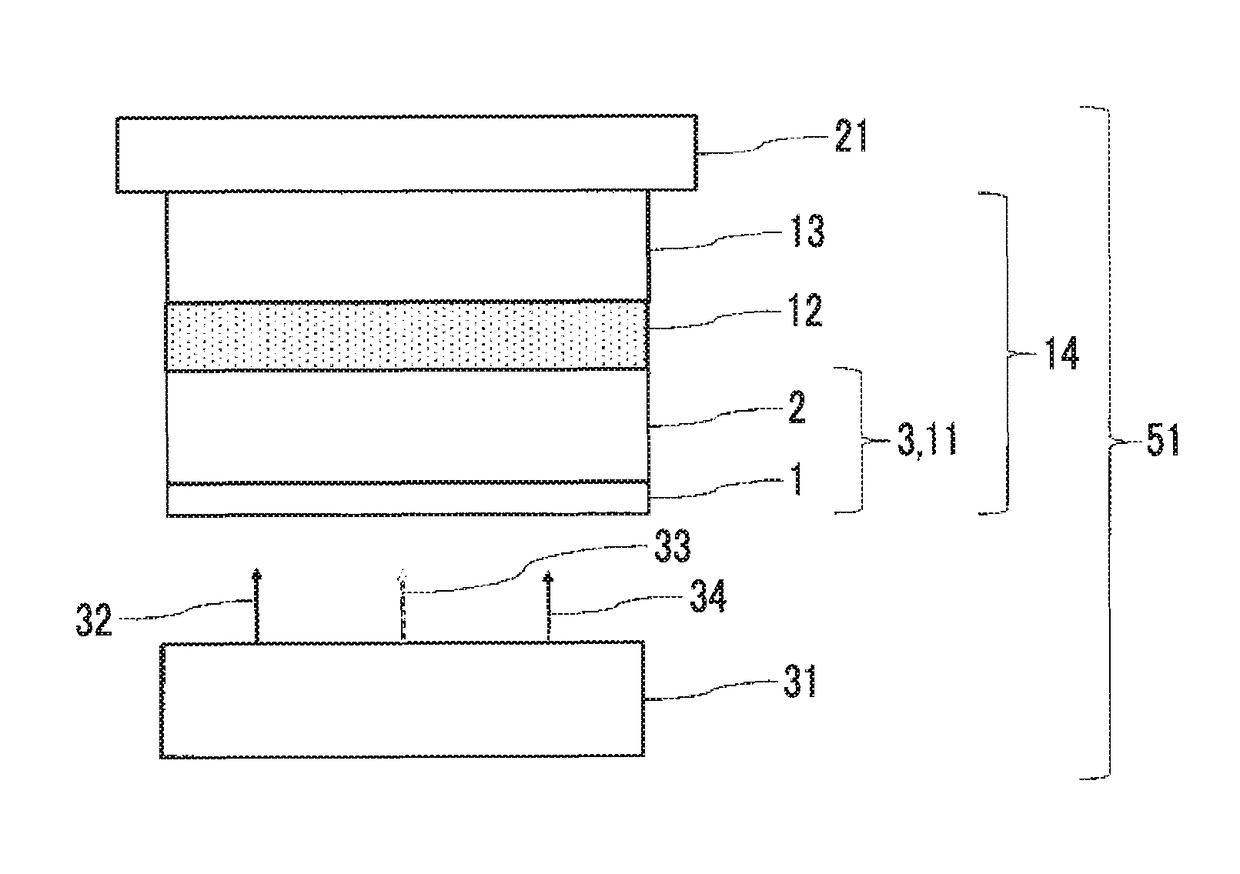
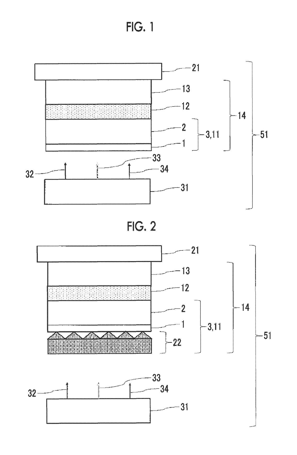
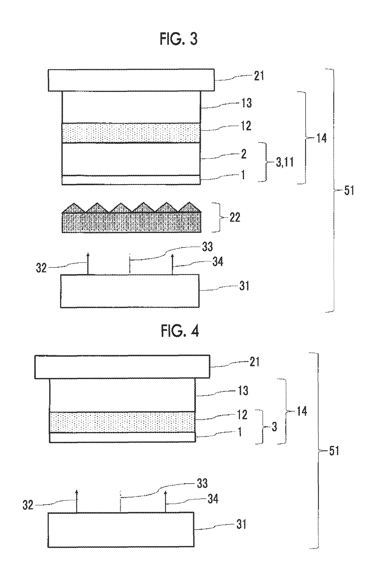
[0237]The coating thickness of the optical thin film when manufacturing the backlight side polarizing plate in Example 1 was changed to the thickness denoted in the following Table 1, and the portion of a peak of a prism of a brightness enhancement film (BEF: manufactured by 3M) which was known as a luminance improvement film was stacked on the laminated body constituted of an optical thin film and a layer directly adjacent to the optical thin film, and only a tip portion of the peak was bonded thereto using an acrylic adhesive. At this time, the above-described luminance improvement film and the above-described optical thin film were bonded to each other so as to have an air interface at least in a part of the surface on the above-described luminance improvement film of the above-described optical thin film.

[0238]The obtained laminated body constituted of the luminance improvement film, the optical thin film, and the layer directly adjacent to the optical thin film was set as an op...

example 17

[0245]An optical film and a backlight side polarizing plate of Example 17 were manufactured in the same manner as in Example 1 except that the acrylic substrate which had been manufactured as described above was used instead of the TAC substrate when manufacturing the laminated body constituted of an optical thin film and a layer directly adjacent to the optical thin film, and the coating thickness of the optical thin film was changed to the thickness denoted in the following Table 1, when manufacturing the backlight side polarizing plate in Example 1.

[0246]

[0247]A liquid crystal display device of Example 17 was manufactured in the same manner as in Example 1 except that a backlight side polarizing plate including the acrylic substrate which had been manufactured as described above was used instead of the backlight side polarizing plate used in Example 1 in manufacturing the liquid crystal display device of Example 1.


PUM

PropertyMeasurementUnit
wavelength rangeaaaaaaaaaa

Abstract

Provided is a liquid crystal display device including a liquid crystal cell, a backlight side polarizer, an optical thin film which forms an air interface, and a backlight unit, in this order. The liquid crystal display device satisfies n (535)<nu (535) and n (535)×d is 1.15-1.25 μm, 1.42-1.52 μm or 1.69-1.79 μm in which n (535) and nu (535) represent a refractive index of the optical thin film and a layer directly adjacent to the optical thin film, respectively, and d represents a thickness of the optical thin film. The liquid crystal display device is capable of matching a peak of light transmittance to light emission peak wavelength of emission line light of RGB. The layer directly adjacent to the optical thin film is the backlight side polarizer or the substrate.

Description

CROSS-REFERENCE TO RELATED APPLICATIONS[0001]This application is a Continuation of PCT International Application No. PCT / JP2014 / 070590, filed on Aug. 5, 2014, which was published under PCT Article 21(2) in Japanese, and claims priority under 35 U.S.C. Section 119(a) to Japanese Patent Application No. 2013-167922 filed on Aug. 12, 2013. The above applications are hereby expressly incorporated by reference, in their entirety, into the present application.BACKGROUND OF THE INVENTION[0002]1. Field of the Invention[0003]The present invention relates to an optical film, a polarizing plate, and a liquid crystal display device. More specifically, the present invention relates to a liquid crystal display device with high light transmittance and high color reproducibility; an optical film used for this liquid crystal display device; and a polarizing plate using this optical film.[0004]2. Description of the Related Art[0005]The application of a flat panel display such as a liquid crystal displ...

Claims


Application Information

Patent Timeline
Patent Type & Authority Patents(United States)
IPC IPC(8): G02B5/30B32B7/02G02B5/20B32B7/00G02B1/11G02F1/1335G02F1/13363
CPCG02F1/133606B32B7/02G02B1/11G02B5/201G02B5/3033G02B5/3083G02F1/13362G02F1/133502G02F1/133621B32B7/00G02F2001/133624B32B2307/40G02B5/3025G02F1/13363G02F1/133528G02F2001/133507G02F2001/133567G02F2001/133614G02F1/133507G02F1/133567G02F1/133624G02F1/133614
Inventor SAITOH, YUKITOOHMURO, KATSUFUMIWATANO, AKIKO
Owner FUJIFILM CORP
Why Eureka
Try Eureka