Switching power supply for RF power amplifiers

a power amplifier and power supply technology, applied in low-noise amplifiers, process and machine control, instruments, etc., can solve problems such as degrading receiver performance, affecting receiver sensitivity, and switching power supplies may be noisy

Inactive Publication Date: 2018-03-20
QUALCOMM INC
View PDF8 Cites 52 Cited by
  • Summary
  • Abstract
  • Description
  • Claims
  • Application Information

AI Technical Summary

Benefits of technology

[0005]In other aspects, a synchronized power supply circuit comprises a first switch connected between a power rail and a first terminal of an inductor that is connected to an RF power amplifier via its second terminal. The circuit also includes a second switch connected between ground and the first terminal of the inductor, and respective gate drivers for the first and second switches. A current sensor of the circuit is connected to the second terminal of the inductor, with an output of the current sensor connected to an input of a comparator. A delay circuit is connected between an output of the comparator and the first and second gate drivers. The delay circuit can delay switch control signals effective to synchronize the power supply circuit.
[0006]In yet other aspects, an apparatus for wireless communication comprises an RF power amplifier and an envelope tracking (ET) power system. The ET power system comprises a switch connected between a power rail and a first terminal of an inductor that is connected to the RF amplifier by its second terminal. The circuit also includes a gate driver connected to a gate of the switch and a class AB amplifier that is connected to the power rail and has an output connected to the RF amplifier. A current sensor is connected between ...

Problems solved by technology

While highly efficient, these switching power supplies may also be noisy due their discontinuous switching operations for power regulation.
Due to the power disparity between transmit and receive signals, the noise generated by the power amplifier that falls in a...

Method used


Image

  • Switching power supply for RF power amplifiers
  • Switching power supply for RF power amplifiers
  • Switching power supply for RF power amplifiers

Examples


example environment

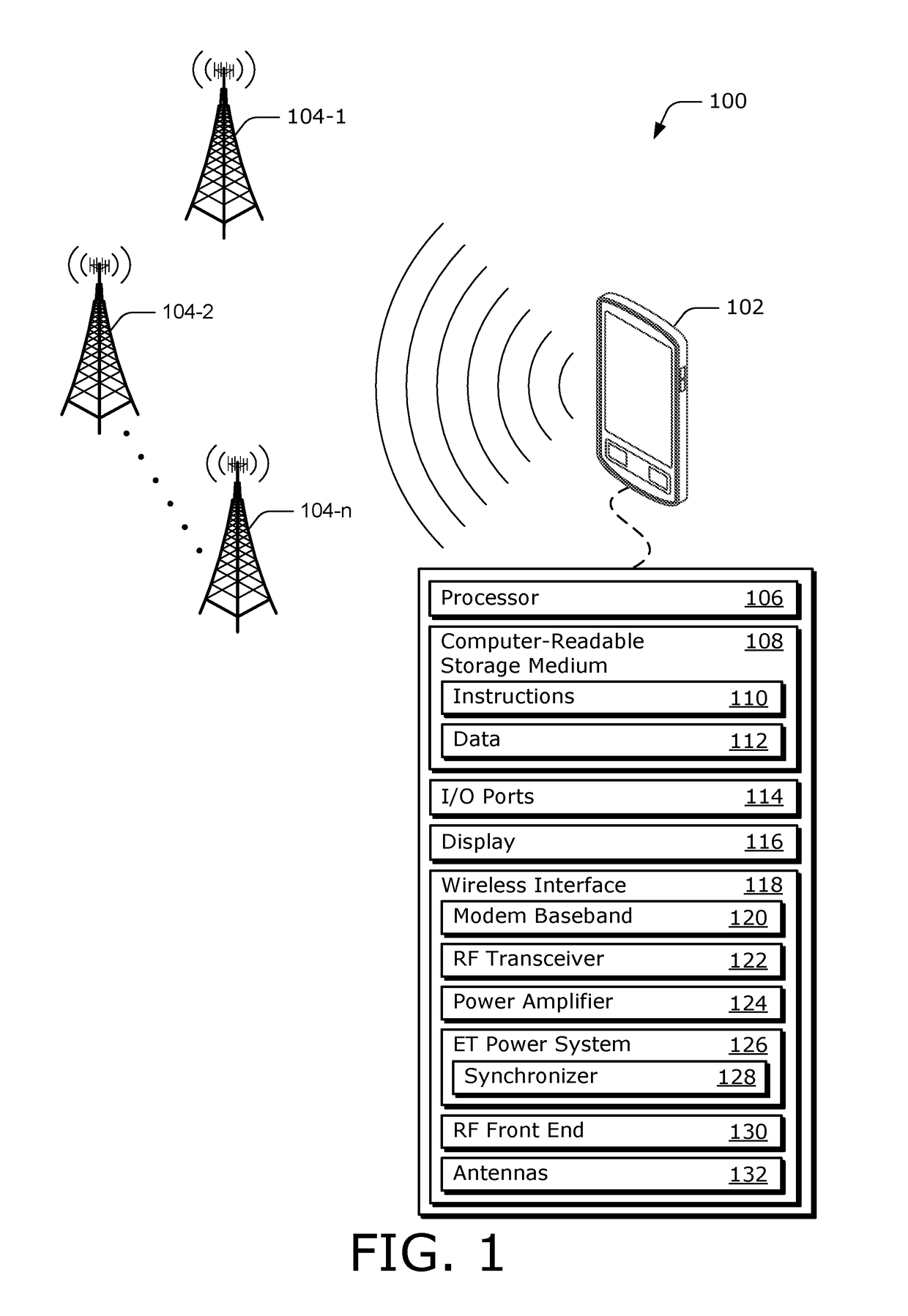
[0026]FIG. 1 illustrates an example environment 100, which includes a computing device 102. In this example, the computing device 102 is implemented as a smart-phone. Although not shown, the computing device 102 may be implemented as any suitable computing or electronic device, such as a modem, cellular base station, broadband router, access point, cellular phone, gaming device, navigation device, media device, laptop computer, desktop computer, server, network-attached storage (NAS) device, smart appliance, vehicle-based communication system, and the like. The computing device 102 communicates data via cell towers 104-1, 104-2, and / or 104-n, which may be configured to provide a wireless network. Although shown as three cell towers, the cell towers 104-1 through 104-n may represent any suitable number of cell towers, where n is any suitable integer.

[0027]The cell towers 104 may communicate with the computing device 102 by transferring a communication link between the computing devic...


PUM


Abstract

The present disclosure describes a synchronized switching power supply for a radio frequency (RF) power amplifier. In some aspects, a synchronized power supply circuit comprises a first switch connected between a power rail and a first terminal of an inductor that is connected to an output of the circuit via its second terminal. The circuit also includes a second switch connected between a ground rail and the first terminal of the inductor, and respective gate drivers for the first and second switches. An amplifier of the circuit is connected to the power rail and has an output connected to the output of the circuit. A current sensor is connected between the output of the amplifier and the output of the circuit, with an output of the current sensor being connected to an input of a comparator. A delay circuit is connected between an output of the comparator and the first and second gate drivers, and may synchronize the power supply circuit.

Description

BACKGROUNDField of the Disclosure[0001]This disclosure relates generally to power circuits for radio frequency (RF) power amplifiers, more specifically, to switch-mode power supply circuits.Description of Related Art[0002]This description of related art is provided for the purpose of generally presenting a context for the disclosure that follows. Unless indicated otherwise herein, concepts described in this section are not prior art to this disclosure and are not admitted to be prior art by inclusion herein.[0003]Radio frequency (RF) transmitters often implement envelope tracking (ET) power systems to improve efficiency of power amplifiers. These ET power systems include highly efficient switch-mode power supplies (SMPS) or switching DC-DC converters that provide power to the power amplifiers. While highly efficient, these switching power supplies may also be noisy due their discontinuous switching operations for power regulation. Switching noise on the power amplifier's incoming po...

Claims


Application Information

Patent Timeline
IPC IPC(8): H03F1/30H03F3/19H02M3/155H02M1/08H03F1/02H03F3/21
CPCH03F1/0222H03F3/21H03F3/19H02M3/155H02M1/08H03F2200/451H03F2200/294H03F2200/105H03F2200/78H03F1/0227H03F3/245H03F2200/102H03F2200/432H03F2200/462
Inventor ABDELFATTAH, MOATAZ ABDELSAMIEMIREA, IULIANSHI, SONG
Owner QUALCOMM INC
Why Eureka
Try Eureka