Bearing with condition monitoring sensor

a condition monitoring and sensor technology, applied in the direction of instruments, mechanical equipment, rotary machine parts, etc., can solve the problems of surface erosion and cavitation within the bearing, hydrogen embrittlement, and failure of the bearing,

Active Publication Date: 2018-04-03
AB SKF
View PDF4 Cites 1 Cited by
  • Summary
  • Abstract
  • Description
  • Claims
  • Application Information

AI Technical Summary

Benefits of technology

[0010]It has also been found that the impedance of the bearing lubricant is generally highest when the bearing lubricant is new and decreases with contamination. Information about the water content and other contaminants in the bearing lubricant can therefore be obtained by measuring the current running through the electrochemical cell. The impedance of the electrochemical cell is proportional to the condition of the bearing lubricant, and the higher the current through the electrochemical cell, the worse the condition will typically be. Oxidization inside the bearing can also reduce the impedance of the bearing lubricant, and measuring the current may therefore provide information about the rate of oxidization processes occurring inside the bearing.
[0011]The present invention makes it possible to make these voltage and current measurements in a very simple, reliable and energy-efficient way, without the need for post-processing of the measured data. Moreover, the components needed to perform the measurements are inexpensive and may be incorporated into existing bearing designs with only minor modifications thereto so that conventional production lines may, to a large extent, still be used.
[0012]One has significant freedom in choosing the positions of the first and second electrically conductive portions inside the bearing, something which makes the bearing arrangement very versatile and easy to adapt to a wide variety of applications. For example, in order to increase the chance of early detection of water in the bearing lubricant, one of the first and second electrically conductive portions may be arranged where water is more likely to accumulate, such as close to a side of the bearing arrangement that will be exposed to rain. Further examples of ways to arrange the first and second electrically conductive portions that may be particularly suitable for some applications follow below.
[0014]According to one embodiment, the bearing is arranged in a housing. The housing protects and seals the bearing from the environment. The housing typically has a relatively large surface area in contact with the bearing lubricant and is therefore suitable as one of the first and second electrically conductive portions.
[0016]According to one embodiment, the second electrically conductive portion is a plating on at least one of the plates. Platings having the desired electrochemical properties are easy to make.
[0017]According to one embodiment, the second electrically conductive portion is a metal strip arranged on the outer race. Metal strips having the desired electrochemical properties are easy to make and also to integrate into bearings with stringent space restrictions.

Problems solved by technology

It has been found that bearing failures are often caused by water in the lubricant.
Water in the lubricant can cause surface erosion and cavitations within the bearing as well as hydrogen embrittlement due to the extreme pressures in rolling element bearings.
Free hydrogen atoms may then penetrate through the surfaces of the bearing components and make them brittle.
Water also speeds up the oxidization of base oil and can cause additives to precipitate and form abrasive particles or sludge.
Despite the efforts that have gone into developing such sensors, many of the systems that are currently available are often complicated and impractical to use in many application.

Method used


Image

  • Bearing with condition monitoring sensor
  • Bearing with condition monitoring sensor
  • Bearing with condition monitoring sensor

Examples


Embodiment Construction

[0022]The present invention will now be described more fully hereinafter with reference to the accompanying drawings, in which currently preferred embodiments of the invention are shown. This invention may, however, be embodied in many different forms and should not be construed as limited to the embodiments set forth herein; rather, these embodiments are provided for thoroughness and completeness, and fully convey the scope of the invention to the skilled person.

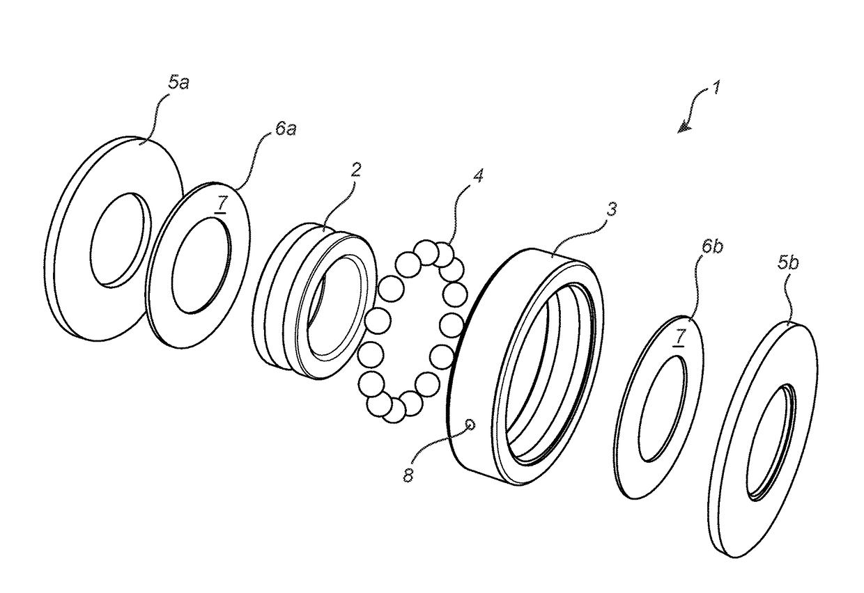
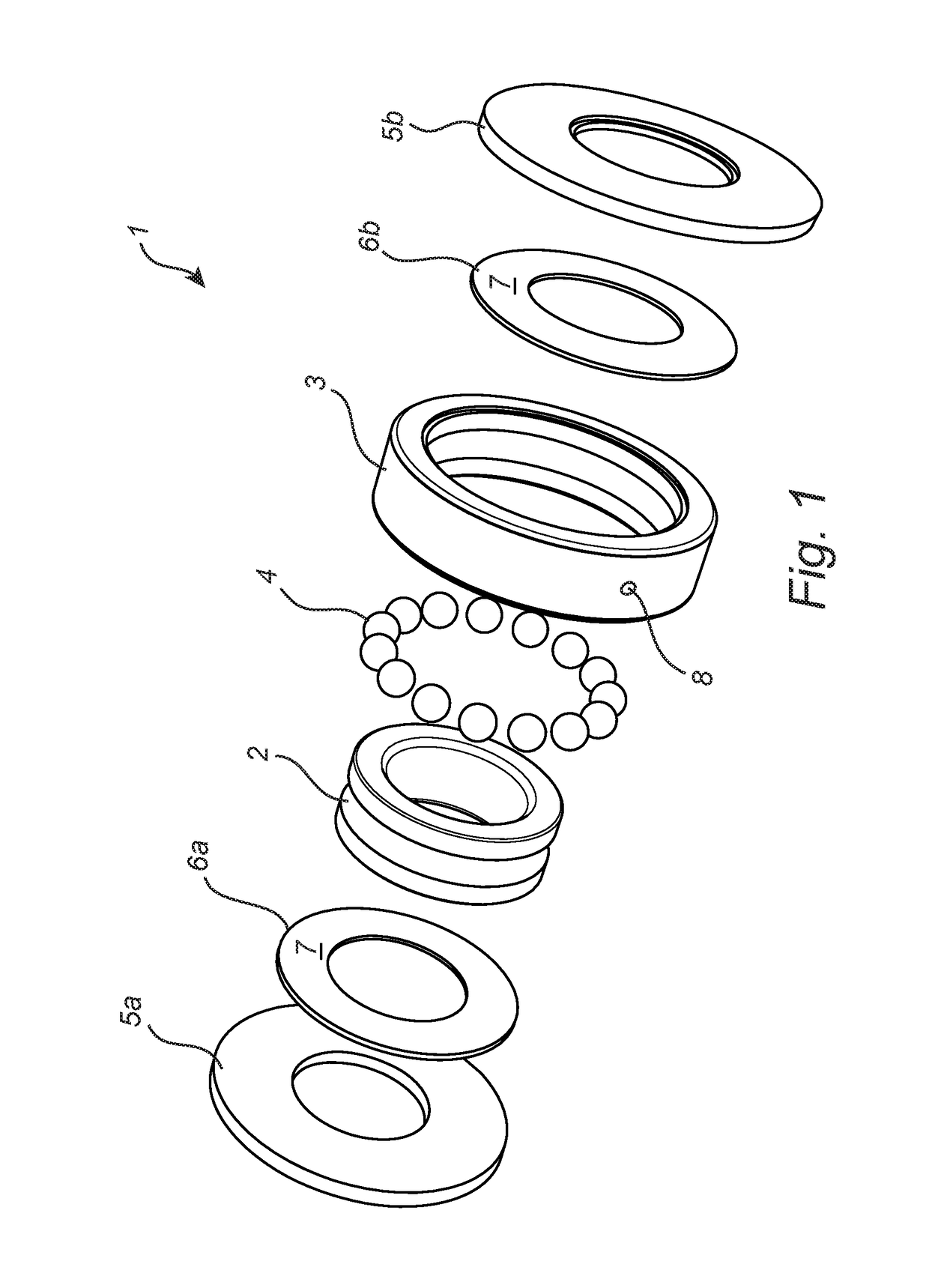
[0023]FIG. 1 shows a bearing arrangement 1 with a bearing that comprises an inner race 2 and an outer race 3 arranged coaxially with each other. Several rolling elements 4 in the form of balls are arranged between the inner and outer races 2, 3. A bearing lubricant (not shown) is arranged in the empty spaces between the inner and outer races 2, 3 so as to reduce friction between the rolling elements 4 and the inner and outer races 2, 3. The bearing lubricant will hereinafter be referred to as the “lubricant”. The bearing fu...


PUM

PropertyMeasurementUnit
electronegativityaaaaaaaaaa
electrically conductiveaaaaaaaaaa
frictionaaaaaaaaaa

Abstract

A bearing arrangement is disclosed. The bearing arrangement includes a bearing with a bearing lubricant. A first electrically conductive portion and a second electrically conductive portion, which have different electronegativities, are in direct contact with the bearing lubricant. The bearing lubricant and the first and second electrically conductive portions form an electrolyte and two electrodes, respectively, of an electrochemical cell. The bearing arrangement further includes a sensor connected to the first electrically conductive portion and to the second electrically conductive portion, the sensor being configured to measure at least one of a current and a galvanic potential between the first and second electrically conductive portions and to determine a water content in the bearing lubricant based on the measurement.

Description

CROSS REFERENCE TO RELATED APPLICATIONS[0001]This application claims priority to Swedish (SE) patent application no. 1551102-5 filed on Aug. 26, 2015, the contents of which are fully incorporated herein by reference.FIELD OF THE INVENTION[0002]The present invention relates to a bearing arrangement that includes a bearing and a sensor for monitoring the condition of the bearing.BACKGROUND OF THE INVENTION[0003]Bearings such as rolling bearings are used in all types of mechanical applications to reduce friction between moving parts. Rolling bearings provide low friction rotation by means of rolling elements arranged between an inner and an outer race. In order to reduce friction and wear between the rolling elements and the races, a bearing lubricant such as grease or oil is often used.[0004]It has been found that bearing failures are often caused by water in the lubricant. Water in the lubricant can cause surface erosion and cavitations within the bearing as well as hydrogen embrittl...

Claims


Application Information

Patent Timeline
Patent Type & Authority Patents(United States)
IPC IPC(8): F16C41/00G01N27/06G01N27/416G01N33/28F16C19/52F16C19/06G01N27/12
CPCF16C41/00F16C19/52F16C19/525G01N27/06G01N33/2888G01N27/4166G01N27/121F16C19/06F16C2202/32F16C2233/00
Inventor DITTES, NICHOLAS
Owner AB SKF
Why Eureka
Try Eureka