Sealed robot drive

a robotic drive and seal technology, applied in the field of sealable robotic drives, can solve the problems of limited size of air gap between the rotor and the stator pole, lack of direct drive technology, and position sensing,

Active Publication Date: 2018-04-17
BOOKS AUTOMATION US LLC
View PDF155 Cites 14 Cited by
  • Summary
  • Abstract
  • Description
  • Claims
  • Application Information

AI Technical Summary

Benefits of technology

[0004]The can-seal generally isolates a motor rotor from a corresponding motor stator via a hermetically sealed non-magnetic wall or “can”, also known as an “isolation wall”. Canseals generally use a non-magnetic vacuum isolation wall that is located between the rotor and stator of a given motor actuator. This allows for the magnetic flux to flow between the rotor and stator across the isolation wall. As a result, the stator can be completely located outside the sealed environment. This may allow for substantially clean and reliable motor actuation implementations in applications such as vacuum robot drives used for semiconductor applications. The limitation of such canseals is that the size of an air gap between the rotor and stator poles may be limited by the isolation wall thickness. For example, the thickness of the isolation wall plus runout tolerances generally imposes constraints on the minimum air gap achievable between the rotor and stator. To increase the efficiency of the motor the gap between the rotor and stator should be minimized however, in cases where the environment sealed or otherwise isolated by the can-seal is exposed to a high or ultra-high vacuum, the isolation wall thickness has to be large enough to provide enough structural integrity to substantially prevent excessive deflection (i.e. the deflection of the isolation may interfere with the operation of the motor). As a result, the efficiency of the motor can be severely decreased due to, for example, the need of larger air gaps between the stator and rotor when compared to robot drive solutions that do not have an isolation wall across the rotor / stator air gap.
[0005]In one aspect, “dynamic seals” may be employed to generally isolate substantially the entire motor from the sealed environment. The dynamic seal may be a seal that allows for a portion of the driven shaft of the motor to operate within the isolated environment. The dynamic seal can be achieved in a number of ways including, for example, lip-seals or a ferro-fluidic seal. However, these dynamic seals may possibly be a source of particle contamination (e.g. from wear and tear of the seal), high friction between the stationary and moving components, limited life and risk of leakage between the sealed environment and, for example, an atmospheric environment outside the sealed environment.
[0008]It would be advantageous to have an isolation wall between the stator and rotor that minimizes the air gap between the stator and rotor. It would also be advantageous to have a vacuum compatible laminated rotor that provides increased magnetic efficiency and / or precision position control.

Problems solved by technology

Generally, existing direct drive technology, which for example uses permanent magnet motors or variable reluctance motors for actuation and optical encoders for position sensing, exhibits considerable limitations when, for example, the magnets, bonded components, seals and corrosive materials of the direct drive are exposed to ultra-high vacuum and / or aggressive and corrosive environments.
The limitation of such canseals is that the size of an air gap between the rotor and stator poles may be limited by the isolation wall thickness.
For example, the thickness of the isolation wall plus runout tolerances generally imposes constraints on the minimum air gap achievable between the rotor and stator.
As a result, the efficiency of the motor can be severely decreased due to, for example, the need of larger air gaps between the stator and rotor when compared to robot drive solutions that do not have an isolation wall across the rotor / stator air gap.
However, these dynamic seals may possibly be a source of particle contamination (e.g. from wear and tear of the seal), high friction between the stationary and moving components, limited life and risk of leakage between the sealed environment and, for example, an atmospheric environment outside the sealed environment.
However, in applications where the sealed environment operates in a high vacuum, the stator coils may outgas undesirable compounds as well as overheat.
As a result, the aforementioned sealing solutions may be expensive and / or impractical.
However, the conventional solid rotors may have an inherent problem of core losses due to, for example, the effect of Eddy currents that result from the rate of change of the phase currents in switched reluctance motor applications.

Method used


Image

  • Sealed robot drive
  • Sealed robot drive
  • Sealed robot drive

Examples


Embodiment Construction

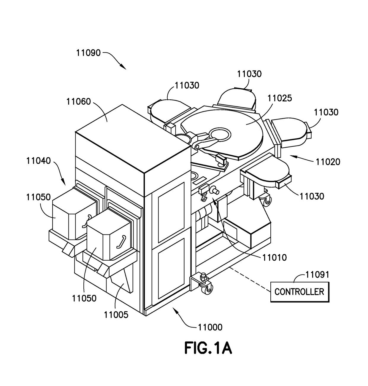
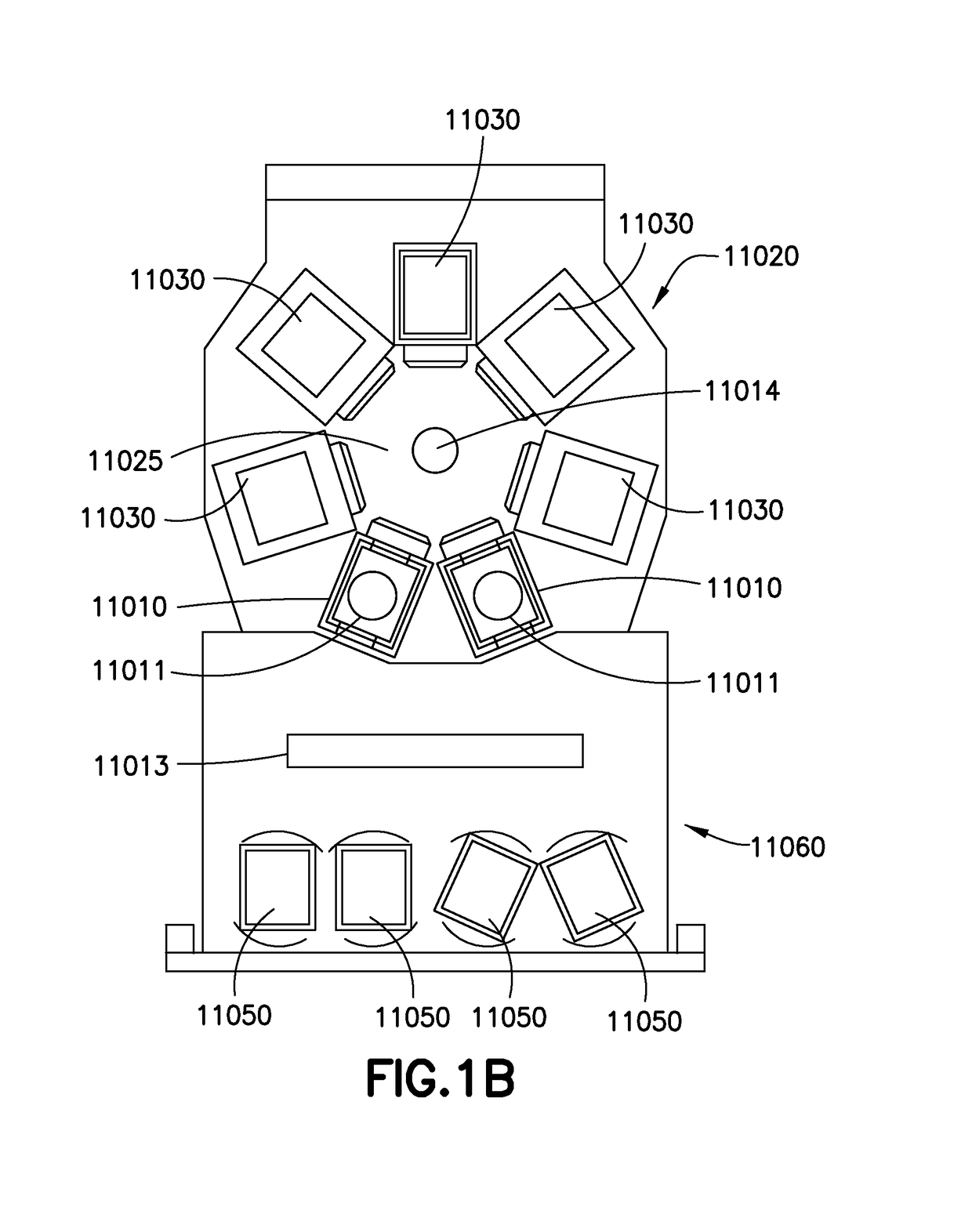
[0039]Referring to FIGS. 1A-1D, there are shown schematic views of substrate processing apparatus or tools incorporating the aspects of the disclosed embodiment as disclosed further herein. Although the aspects of the disclosed embodiment will be described with reference to the drawings, it should be understood that the aspects of the disclosed embodiment can be embodied in many forms. In addition, any suitable size, shape or type of elements or materials could be used.

[0040]Referring to FIGS. 1A and 1B, a processing apparatus, such as for example a semiconductor tool station 11090 is shown in accordance with an aspect of the disclosed embodiment. Although a semiconductor tool is shown in the drawings, the aspects of the disclosed embodiment described herein can be applied to any tool station or application employing robotic manipulators. In this example the tool 11090 is shown as a cluster tool, however the aspects of the disclosed embodiment may be applied to any suitable tool sta...


PUM


Abstract

A transport apparatus including a housing, a drive mounted to the housing, and at least one transport arm connected to the drive where the drive includes at least one rotor having at least one salient pole of magnetic permeable material and disposed in an isolated environment, at least one stator having at least one salient pole with corresponding coil units and disposed outside the isolated environment, where the at least one salient pole of the at least one stator and the at least one salient pole of the rotor form a closed magnetic flux circuit between the at least one rotor and the at least one stator, and at least one seal configured to isolate the isolated environment where the at least one seal is integral to the at least one stator.

Description

CROSS-REFERENCE TO RELATED APPLICATIONS[0001]This application is a non-provisional of and claims the benefit of U.S. provisional patent application No. 61 / 903,813 filed on Nov. 13, 2013, the disclosure of which is incorporated herein by reference in its entirety.BACKGROUND1. Field[0002]The exemplary embodiments generally relate to robotic drives and, more particularly, to sealed robotic drives.2. Brief Description of Related Developments[0003]Generally, existing direct drive technology, which for example uses permanent magnet motors or variable reluctance motors for actuation and optical encoders for position sensing, exhibits considerable limitations when, for example, the magnets, bonded components, seals and corrosive materials of the direct drive are exposed to ultra-high vacuum and / or aggressive and corrosive environments. To limit exposure of, for example, the magnets, bonded components, seals and corrosive materials of the direct drive a “can-seal” is generally used.[0004]The...

Claims


Application Information

Patent Timeline
Patent Type & Authority Patents(United States)
IPC IPC(8): H02K5/128B25J11/00H02K11/00H02K1/14H02K19/10H02K11/21H02K1/24
CPCH02K5/128B25J11/0095H02K1/14H02K1/141H02K19/103H02K1/24H02K1/246H02K11/21H02K1/148H02K11/215H02K2201/03
Inventor MOURA, JAIRO T.GILCHRIST, ULYSSESCAVENEY, ROBERT T.
Owner BOOKS AUTOMATION US LLC
Why Eureka
Try Eureka