Atomic force microscopy

a technology of atomic force and microscopy, which is applied in the direction of mechanical measurement arrangements, mechanical roughness/irregularity measurements, instruments, etc., can solve the problem of tiny deflection of cantilever beams, and achieve the effect of simplifying the arrangement, and reducing the cost of optical fiber

Inactive Publication Date: 2001-07-31
IBM CORP
View PDF46 Cites 11 Cited by
  • Summary
  • Abstract
  • Description
  • Claims
  • Application Information

AI Technical Summary

Benefits of technology

The present invention relies upon the measurement of the cantilever beam orientation rather than displacement. A change in position is transformed into an angular change which is inversely proportional to the length of the cantilever. In prior art atomic force microscopes the length of the cantilever beam has been on the order of 1 mm. The micromachined cantilever beam employed in the present invention is on the order of 100 microns in length thereby enabling atomic resolution of the surface to be investigated. When practicing the invention in an environment not requiring a vacuum, simplifications to the arrangement are possible. For example, the optical fiber can be eliminated, resulting in a more compact design. Also, the inertial mover is not required since the microscope components are accessible.
Preferably, the output of the visible diode laser is an elliptical beam with an aspect ratio in the range of approximately 5 to 7:1. While such ellipiticity is generally considered undesirable requiring optical correction, the asymmetric beam shape is advantageously used in practicing the present invention. By appropriately focussing the laser beam on a rectangular cantilever beam, increased sensitivity of the laser beam deflection measurement and a simplified alignment procedure are achieved. An additional advantage of the elliptical beam resides in the ability to use a laser with higher laser power, without exceeding the saturation limit of the bicell, and thereby achieve higher measurement sensitivity. It is also possible to reduce the distance between the cantilever beam and the bicell, thus making the atomic force microscope even more compact. In cases where the beam is not inherently elliptical, as in the case of the light output from an optical fiber, a cylindrical lens can be used to achieve the advantageous elliptical shape.

Problems solved by technology

The attractive or repulsive forces occurring between the atoms at the apex of the tip and those of the surface result in tiny deflections of the cantilever beam.

Method used


Image

  • Atomic force microscopy
  • Atomic force microscopy
  • Atomic force microscopy

Examples


Embodiment Construction

Atomic force microscopes are known in the art as described, for example, in U.S. Pat. No. 4,724,318 issued to G. Binnig and assigned to the same assignee or the present invention, which patent is incorporated herein by reference. While the Binnig patent describes a method of measuring the tip to surface distance by means of monitoring the tunneling current, the present invention measures the tip orientation by optical-beam-deflection, as will be described hereinafter. The present invention is most advantageous for operation in an inaccessible environment, such as in a vacuum or an ultrahigh vacuum, due to the provision of a remotely positionable position-sensitive detector.

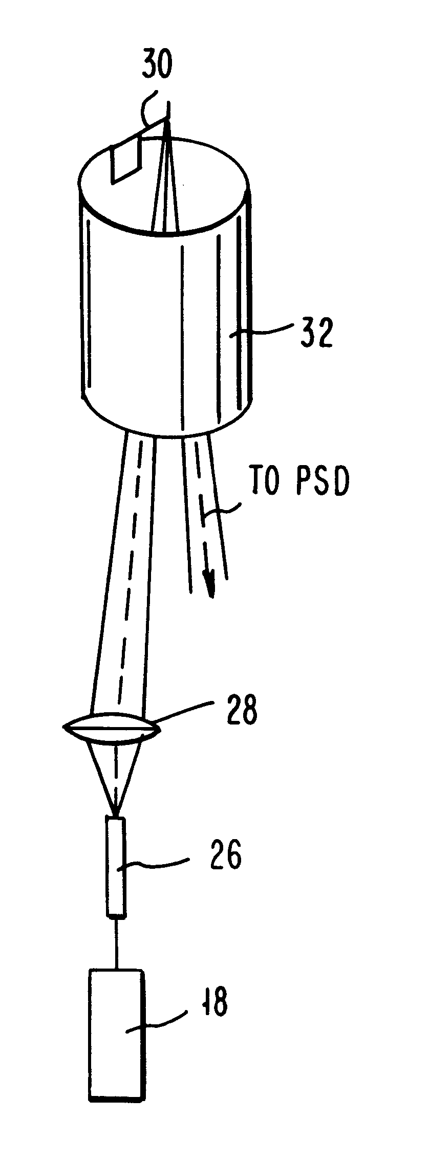
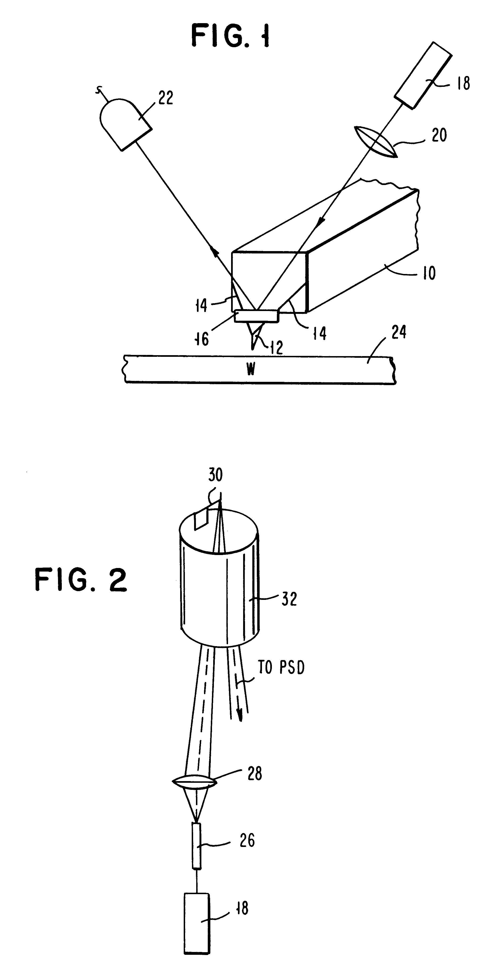
Referring now to the figures and to FIG. 1 in particular, there is shown a schematic representation of a cantilever beam deflection detection scheme. A stylus-cantilever system includes a cantilever beam 10 made of, e.g., silicon or silicon nitride, having a tip 12 of a length in the range between 1 and 10 microns...


PUM

PropertyMeasurementUnit
lengthaaaaaaaaaa
lengthaaaaaaaaaa
aspect ratioaaaaaaaaaa

Abstract

An atomic force microscope includes a tip mounted on a micromachined cantilever. As the tip scans a surface to be investigated, interatomic forces between the tip and the surface induce displacement of the tip. A laser beam is transmitted to and reflected from the cantilever for measuring the cantilever orientation. In a preferred embodiment the laser beam has an elliptical shape. The reflected laser beam is detected with a position-sensitive detector, preferably a bicell. The output of the bicell is provided to a computer for processing of the data for providing a topographical image of the surface with atomic resolution.

Description

BACKGROUND OF THE INVENTIONThe present invention relates to atomic force microscopy and specifically to an atomic force microscope which employs a micromachined cantilever beam in order to achieve atomic resolution. In addition, the atomic force microscope is capable of operation in vacuum, air or liquid environments, of scanning a large surface area and of providing common mode rejection for improved operation.Atomic force microscopy is based upon the principle of sensing the forces between a sharp stylus or tip and the surface to be investigated. The interatomic forces induce the displacement of the stylus mounted on the end of a cantilever beam. In its original implementation, a tunneling junction was used to detect the motion of the stylus attached to an electrically conductive cantilever beam. Subsequently, optical interferometry was used to detect cantilever beam deflection.As described by G. Binnig et al, in Phys. Rev. Lett., vol. 56, No. 9, March 1986, pp. 930-933, a sharply...

Claims


Application Information

Patent Timeline
Patent Type & Authority Patents(United States)
IPC IPC(8): G12B21/08G12B21/00G12B21/02G01B7/34G01B11/30G01B21/30G01N37/00G01Q20/02G01Q20/04G01Q60/24
CPCB82Y35/00G01Q20/02Y10S977/87
Inventor AMER, NABIL MAHMOUDMEYER, GERHARD
Owner IBM CORP
Why Eureka
Try Eureka