Patient infusion system for use with MRI

a patient and infusion system technology, applied in the field of mri systems, can solve the problems of interference between the high-power magnetic field, mri systems which employ these solutions require substantial site dedication and are therefore not very portable, and the alternative has not proven to be optimal

Inactive Publication Date: 2002-03-26
BAJER MEDIKAL KEHA INK
View PDF48 Cites 101 Cited by
  • Summary
  • Abstract
  • Description
  • Claims
  • Application Information

AI Technical Summary

Benefits of technology

The invention comprises an improved magnetic resonance imaging system which decreases the amount of electromagnetic interference that has heretofore been found within a MRI isolation suite while increasing the portability and ease of system installation. The invention reduces deleterious interaction between the imaging magnetic field and the magnetic field generated by the electric motors which control and operate contrast media injectors.
In the preferred embodiment, this communication link is made through a window in the isolation room barrier. These windows are typically in the form of a glass laminate containing a conductive wire mesh, or alternatively, a window that is coated with a thin sheet of conductive material such as gold to maintain the shielding characteristics of the isolation room. The communications link consists of electromagnetic transceivers which operate in a frequency range which permeates the window while maintaining the integrity of the isolation barrier. Infrared or electromagnetic energy in the visual range provide the best results. Alternatively, a fiberoptic communication link can be used to provide the communication link, since fiberoptics do not create electromagnetic radiation.
The present invention also incorporates a contrast media injection unit located within the shielded room which comprises separate contrast media injector head and injection head control unit. The contrast media injection head, and specifically the syringe pistons are located in close proximity to the patient and consequently are located within the powerful magnetic field used to generate the magnetic resonance image. The head control unit which controls operation of the injector head is located from 10-15 feet away from the injector head control unit. The head control unit incorporates electric motors to control and to operate the pistons of syringes used for the injection of patients. A non-rigid operating drive connects the electric motors and control unit to the syringe pistons located on the injection head. In a preferred form, the drive connection can be by way of flexible shafts. Each flexible drive shaft forms a mechanical link between an electric motor located on the head control unit and a piston of the syringes on the injector head. Alternatively, a hydraulic system could be used to control the piston of the injector head. In the preferred embodiment, the flexible drive shaft is manufactured from a non-ferrous metal such as hard brass. The distancing of the head control unit and drive motors from the injector head decreases the adverse effects that the imaging magnetic field has on the electric motors of the injectors and conversely, the adverse affects of spurious electromagnetic radiation arising from operating of the electric motors used to control and operate the contrast media injectors is also reduced significantly.

Problems solved by technology

The external, isolated location of the system controller creates various problems associated with the installation and operation of these systems.
One such problem is the need to provide a communications link between the externally located controller and the contrast media injectors, without introducing extraneous electromagnetic radiation.
These alternatives have proven to be less than optimum, since spurious radiation arose from the presence of the various supply cables within the shielded imaging suite.
Additionally, MRI systems which employed these solutions required substantially site dedication and were therefore not very portable.
Another problem associated with conventional magnetic resonance imaging systems is the interference which occurs between the high power magnetic field used for generating the magnetic resonance image and the magnetic fields created by the electric motors which control the operation of the contrast media injection heads.
The magnetic field generated by the magnet of the magnetic resonance imaging system is extremely powerful and adversely affects the operation of the electric motors used in the injector head.
Additionally, operation of the electric motors in close proximity to the magnetic field used to generate the magnetic resonance image also has an adverse impact on the quality of the resulting image.
The close proximity of the electric motors to the magnetic field used for generating the magnetic resonance image typically resulted in a decrease in motor performance and the ability to control the electric motors used in the injector heads, as well as an overall decrease in system performance.

Method used


Image

  • Patient infusion system for use with MRI
  • Patient infusion system for use with MRI
  • Patient infusion system for use with MRI

Examples


Embodiment Construction

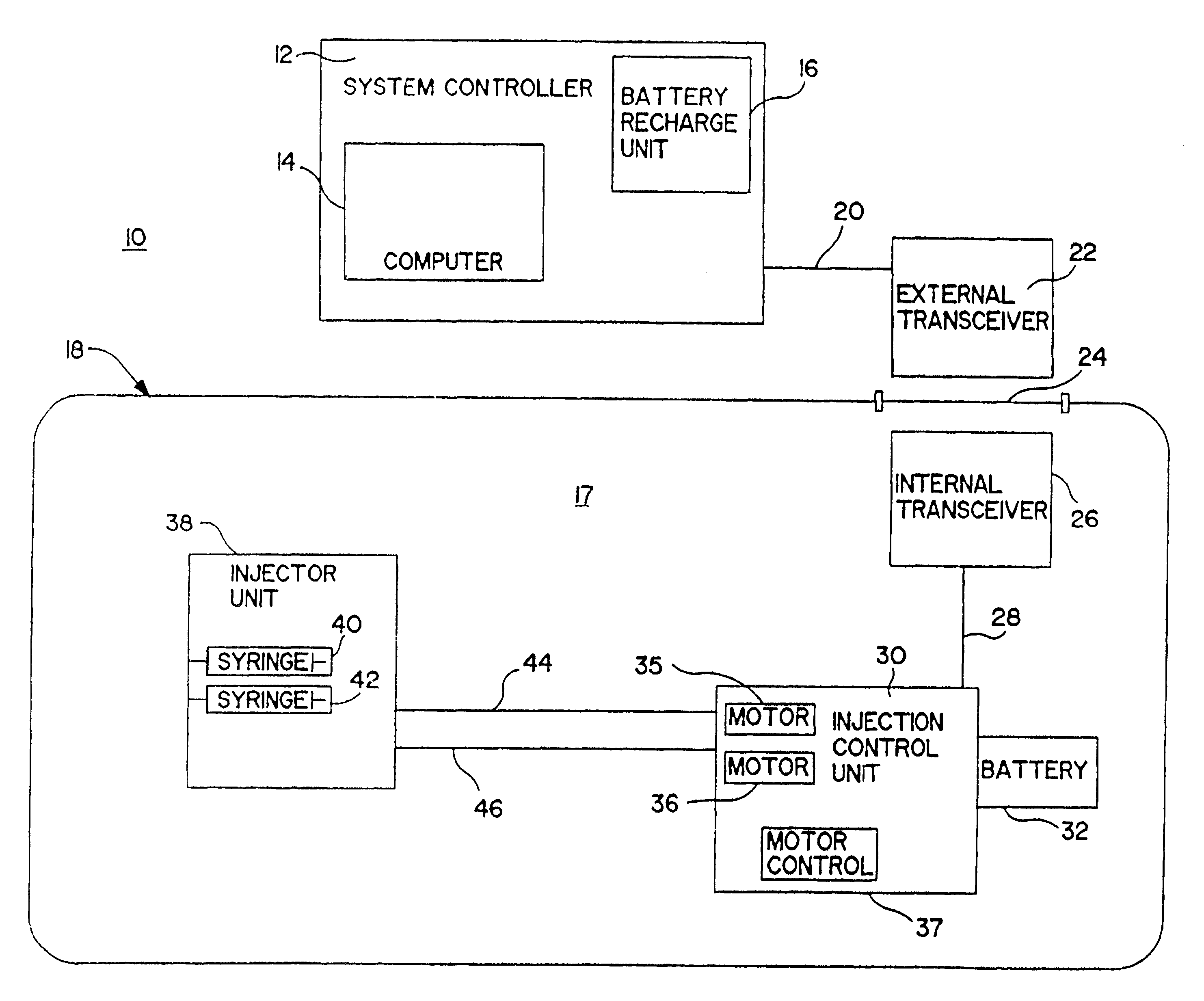
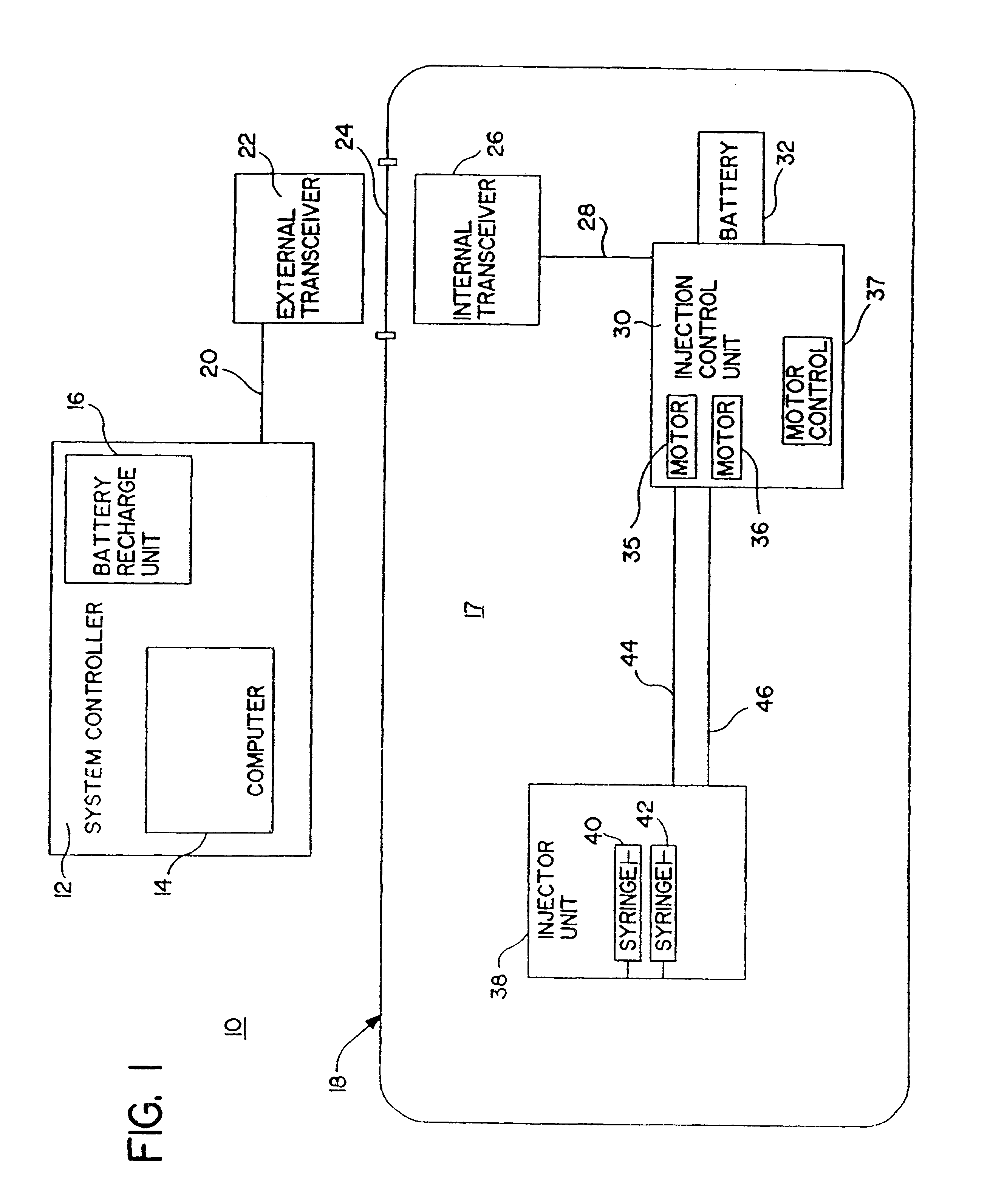
FIG. 1 illustrates an improved magnetic resonance imaging system according to the present invention and is shown generally at 10. The MRI system includes a system controller 12 which incorporates a computer 14 and a battery charging unit 16. The system controller 12 is located externally of the imaging room 17, the imaging room being shielded from electromagnetic interference by a shield 18. Isolation can be achieved by completely enclosing the room with copper sheet material or some other suitable, conductive layer such as wire mesh. Communication line 20, connects the system controller 12 with an external infrared / optical communications transceiver 22. The shielded imaging room 17 also incorporates a patient viewing window 24 in the shield 18 which allows an observer to view the room without breaching the electromagnetic shield 18. The window 24 can be formed by sandwiching a wire mesh material (not shown) between sheets of glass or coating the window with a thin coating of conduc...


PUM


Abstract

This invention relates generally to the field of Magnetic Resonance Imaging (MRI) systems for generating diagnostic images of a patient's internal organs and more particularly, this invention relates to improved MRI systems with decreased interference between the magnetic field used for producing diagnostic images and the magnetic fields generated by the electric motors used for driving the pistons of the contrast media injectors. Additionally, the system employs an improved communication link between an externally located system controller and the injection head control unit located within the electromagnetic isolation barrier which defines the magnetic imaging room.

Description

BACKGROUND OF THE INVENTION1. Field of the InventionThis invention relates generally to the field of Magnetic Resonance Imaging (MRI) systems for generating diagnostic images of a patient's internal organs and more particularly, this invention relates to improved MRI systems exhibiting decreased interference between the magnetic field used for producing diagnostic images and spurious magnetic fields created by ancillary equipment, such as the electric motors used for driving the pistons of the contrast media injectors. Additionally, the system employs an improved communication link between an externally located system controller and the injection head control unit which is located within the electromagnetic isolation barrier of the magnetic imaging suite.2. Description of the Related ArtIt has become recognized that MRI systems require isolation from external sources of electromagnetic fields, if optimum image quality is to be obtained from MRI diagnostic procedures. Conventional MR...

Claims


Application Information

Patent Timeline
Patent Type & Authority Patents(United States)
IPC IPC(8): A61M5/145A61M5/00A61B5/055G01R33/42G01R33/28G01R33/421
CPCA61M5/007A61M5/14546G01R33/28G01R33/281G01R33/283G01R33/285G01R33/421Y10S128/01
Inventor UBER, III, ARTHUR E.WADDELL, SEIDSTULEN, JOHNMANLEY, JON E.DEDOLA, SALVATORE J.NEWELL, GORDON C.
Owner BAJER MEDIKAL KEHA INK
Why Eureka
Try Eureka