
Data processing system and method for detecting mandatory relations violation in a relational database

a data processing system and database technology, applied in relational databases, instruments, transportation and packaging, etc., can solve the problems of requiring a substantial amount of time for requiring thousands of seconds (many hours) to retrieve a desired piece of information, and wasting time on the search and retrieval process, etc., to achieve easy expansion or restructuration, high speed

Inactive Publication Date: 2008-04-08
FINANCIAL SYST TECH
View PDF47 Cites 29 Cited by
  • Summary
  • Abstract
  • Description
  • Claims
  • Application Information

AI Technical Summary

Benefits of technology

[0031]It is an objective of the present invention to provide a database system which is capable of storing voluminous amounts of information, sifting through the information at high speed, and is at the same time easily expandable or restructurable to take on new forms of entities and relationships.
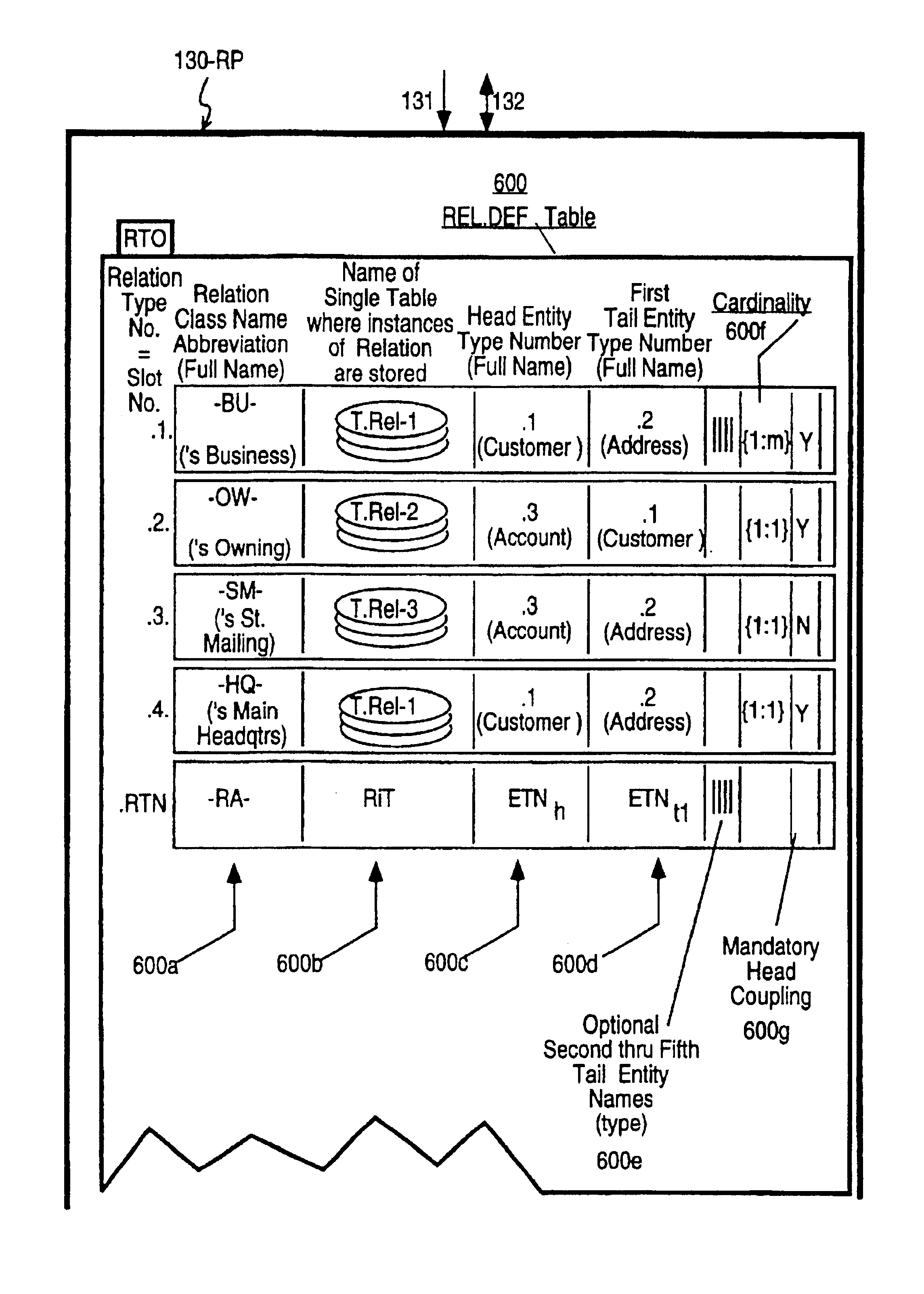
[0032]In accordance with a first aspect of the invention, an entity definition table (ENT.DEF) is defined within the memory means of a computer system to store the name of an allowed entity type (class) and the name of a single other table (Entity-instances Table or “EiT” for short) where instances of the allowed entity type may be stored. A separated relationships definition table (REL.DEF) is defined in the memory means to list in each row of the table: (a) the name of an allowed relations type, (b) the name of a single Relation-instances Table (RiT) where instances of the allowed relationship type may be stored, (c) the name of a primary (head) entity type to which the relation type may apply and (d) the names of one or more secondary (tail) entity types to which the named relationship may apply. Each row of the Relation-instances Table (RiT) is provided with at least one primary pointer which points to the storage location of a first instance of the primary entity type and at least one secondary pointer which points to the storage location of a corresponding first instance of the secondary entity type. Each row of the Relation-instances Table (RiT) further includes a pointer to a relationship-defining row in the REL.DEF table. The pointer can be the name of an applicable relation type as recorded in the REL.DEF table. Relationships between instances of a primary entity and a secondary entity are thus expressly defined by entries in the Relation-instances Table (RiT). Adding new rows to this Relation-instances Table (RiT) allows for the addition of new relations. Adding new rows to the REL.DEF table allows for the creation of new classes (types) of relationships. Since relation-defining tables can be updated using a fixed set of update modules, reprogramming at the source or assembly level is not needed for restructuring the schema of the database.

Problems solved by technology

Despite this capability, it may take an undesirably long time (i.e., hours or days) to retrieve desired pieces of information.
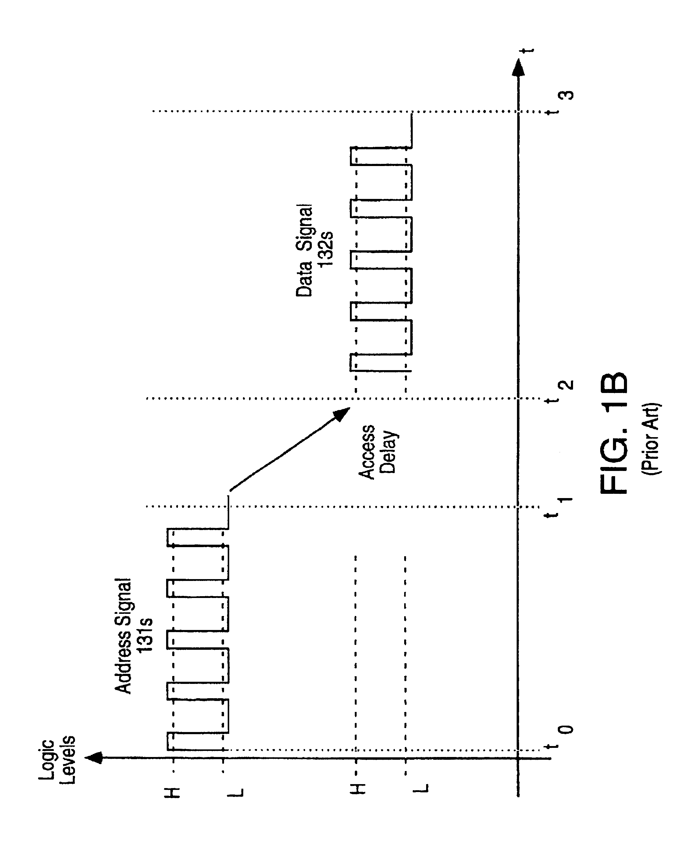
Thus, even at speeds of one million examinations per second, it can take thousands of seconds (many hours) to retrieve a desired piece of information.
However, if a library user has an inquiry which is not keyed to an author's name, the search and retrieval process can require substantially more time; the worst case scenario being that for each inquiry the librarian has to physically sift through and examine each card in the entire catalog.
Although it is conceptually possible to answer this inquiry using the information within the catalog, the time for such a search may be impractically long, and hence, while the information is theoretically available, it is not realistically accessible.
This form of redundant storage is disadvantageous because the size of the card catalog is doubled and hence, the cost of information storage is doubled.
In such cases, a great deal of work previously expended to create the catalog system may have to be discarded and replaced with new work.
It might be that the just revised and enlarged second card system does not have the capacity to handle the demands of the newer technology or regulation.
Time after time, a system will be built up only to be later scrapped because it fails to anticipate a new type of information storage and retrieval operation.
This is quite wasteful.
As more and more accesses are required to fetch pointers and keys leading to the memory location of a piece of sought-after information (“real data”), the response time to an inquire increases and system performance suffers.
Despite these advantages, relational database systems suffer from expandability and restructuring problems similar to those of the above-described manual system.
This is not easily done.
It was time consuming, costly and prone to programming errors.

Method used


Image

  • Data processing system and method for detecting mandatory relations violation in a relational database
  • Data processing system and method for detecting mandatory relations violation in a relational database
  • Data processing system and method for detecting mandatory relations violation in a relational database

Examples


embodiment 200

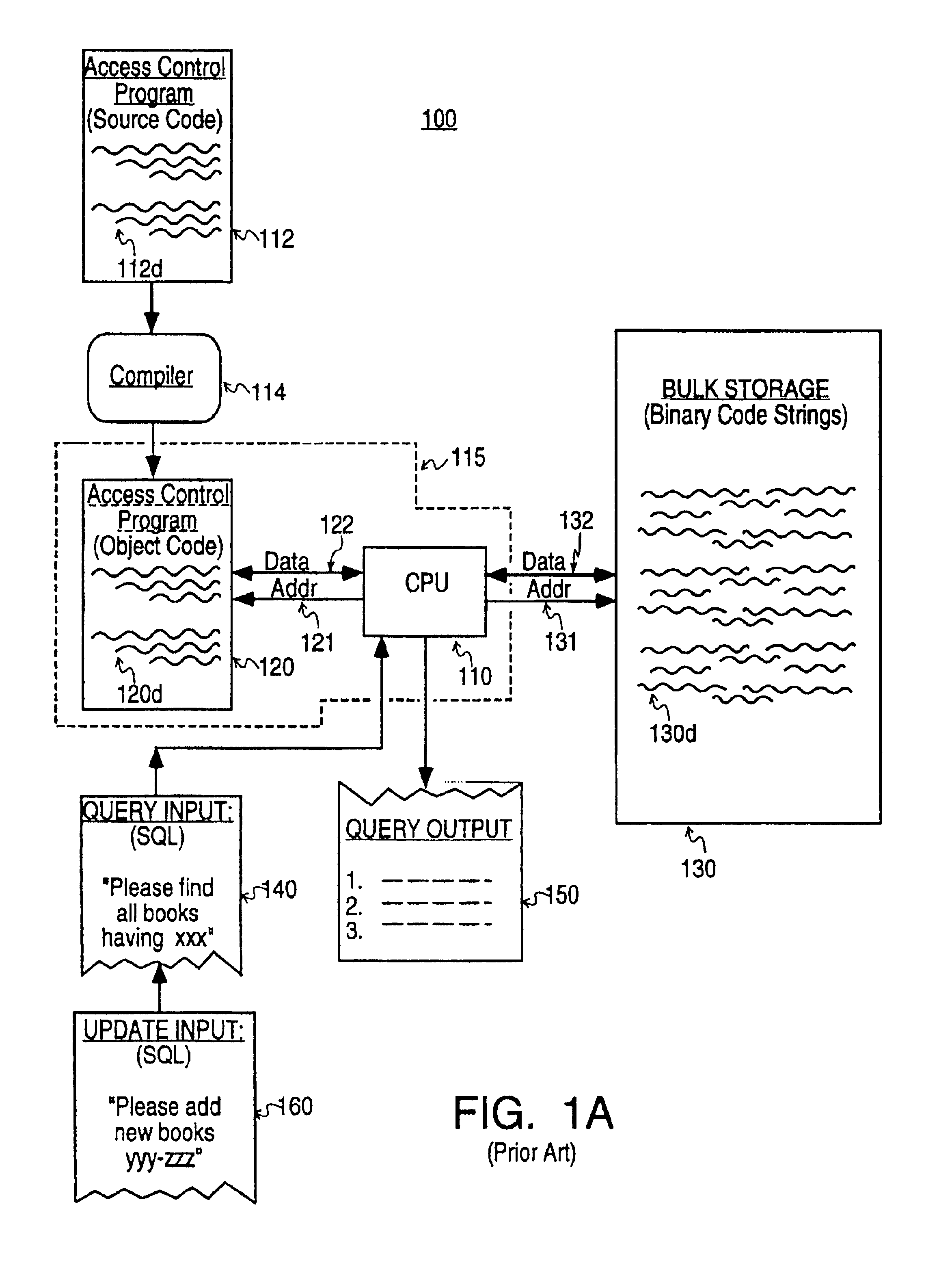
[0059]The implied relations between the “real” data boxes, 231, 233 and 235 of Record No. 1, arise only after “meaning” is assigned to all the boxes 231-236. Such “meaning” comes from the operation of the search-and-translation machine 115 (FIG. 1). To understand this concept, assume that an automated “searching” machine (computer) 115 / 200 of embodiment 200 is examining the data string 230 held within the single Record No. 1. Assume further that this searching machine 115 / 200 includes means for assigning appropriate “meanings” to each of the data subportions contained in each of subsections 231-236 to thereby designate some as containing “real” data and others as containing “ancillary” (e.g., pointer) data. In that case the search machine 115 / 200 can scan horizontally across the record, parse the data string 230 into subsections of appropriate size and extract the name of the book's author, the book's title and the location of the book within the library, as desired. On the other ha...

embodiment 300

[0077]Each row (e.g., row 4) within the third table 330 implicitly creates a set of logical links or “relations”, L41-P42-L43, which join a person's name to a particular home address. These links, L41, P42 and L43 are represented in FIG. 3 by dashed connecting lines which, in combination, join the Person's-Name held in table 310, row N, to the Home-Address held in table 320, row 2. The implied linkage, L41-P42-L43, does not arise from the contents of the first three tables, 310, 320 and 330 taken alone. The key numbers (e.g., N-IDN, H-IDN, P-IDN) that are held within these tables are by themselves a meaningless series of numbers. It is only when randomly distributed modules of object code 120d* stored within the memory means 120 of this “relational database” system (300) cooperatively interact with the CPU 110 that the implied relations come into being. The object code 120d* instructs the CPU 110 to select a specific row (i.e., row 4) in the third table 330, to extract the numbers f...


PUM


Abstract

Machine automated techniques are described for a method of data processing called Relationships Processing. A computing system is disclosed which provides for the high speed recording and extraction of data objects (entities) and for the development of data representing a queried relationship between the entities. Furthermore, methods and systems are disclosed to detect mandatory relations violation between entities by examining whether certain relations exist. The system is expandable to handle the relatively voluminous data bases of large commercial data repositories. A user defines a set of entities and allowed relationships between the entities. The user can expand this set of allowed entities and relationships at any time during the life of the system without reprogramming or compiling of computer program code or disrupting concurrent operational use of the system. Large systems can now be built that are no longer limited to the scope of design requirements known during initial system development. For a given set of defined relationships the system allows the user to perform complex inquiries (again without programming at the code level) that would normally require multiple nested inquiries to be coded programmatically and would not achieve the performance levels of the Relationships Processor.

Description

[0001]This application is a division of application Ser. No. 08 / 083,36108 / 083,861, filed Jun. 28, 1993, now abandonedU.S. Pat. No. 5,604,899, which issued on Feb. 18, 1997, which is a continuation of Ser. No. 07 / 526,424, filed May 21, 1990, now abandoned.BACKGROUND OF THE INVENTION[0002]1. Cross Reference to Microfiche Appendix[0003]This application includes a plurality of computer program listings (modules) in the form of a Microfiche Appendix which is being filed concurrently herewith as 1162 frames (not counting target and title frames) distributed over 20 sheets of microfiche in accordance with 37 C.F.R. § 1.96. The disclosed computer program listings are incorporated into this specification by reference but it should be noted that the source code and / or the resultant object code of the disclosed program modules are subject to copyright protection. The copyright owner has no objection to the facsimile reproduction by anyone of the patent document (or the patent disclosure as it ...

Claims


Application Information

Patent Timeline
Patent Type & Authority Patents(United States)
IPC IPC(8): G06F17/30G06F1/00G06F15/00
CPCG06F17/30604Y10S707/99931Y10S707/99952Y10T428/1005Y10S707/99933Y10S707/99934Y10S707/954Y10S707/99932G06F16/288C09K2323/02
Inventor DOKTOR, KAROL
Owner FINANCIAL SYST TECH
Learn More