Conveyor oven having an energy management system for a modulated gas flow

a technology of energy management system and conveyor oven, which is applied in the direction of gaseous heating fuel, domestic stoves or ranges, furnaces, etc., can solve the problems of sharp increase in the cost of natural or propane gas for the burners, and achieve the effects of improving reliability, and reducing the cost of natural or propane gas

Inactive Publication Date: 2011-12-20
MIDDLEBY MARSHALL
View PDF95 Cites 18 Cited by
  • Summary
  • Abstract
  • Description
  • Claims
  • Application Information

AI Technical Summary

Benefits of technology

The integrity of the safety features built into the oven is preserved by an isolation in the electrical control circuit between the elements which control the modulating valve and a conditioner which converts signals from sensors into signals which can enable an operation of the modulating valve. This isolation prevents feed back which might otherwise cause the modulating valve to behave in a way which would defeat the shutdown of an on/off safety valve. In order to provide a self-healing of this integrity insuring system, it uses transformers for separating and isolating the modulation valve control and conditioner circuits from an ignition control module.
The advantages of the inv

Problems solved by technology

Also, the cost of the fuel (natural or propan

Method used


Image

  • Conveyor oven having an energy management system for a modulated gas flow
  • Conveyor oven having an energy management system for a modulated gas flow
  • Conveyor oven having an energy management system for a modulated gas flow

Examples


Embodiment Construction

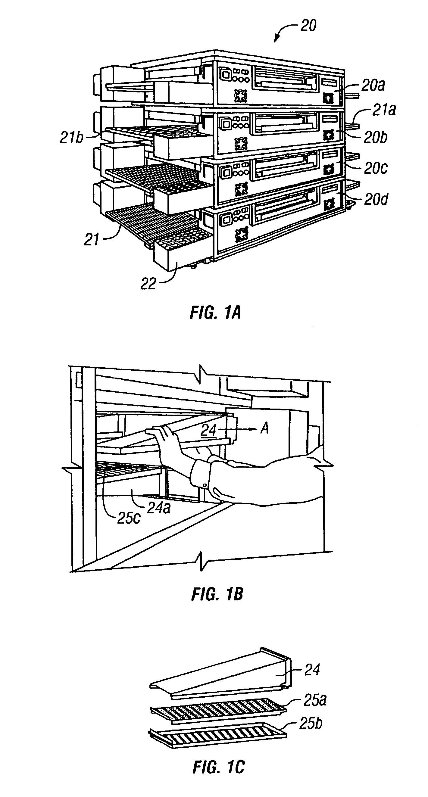
The equipment in FIGS. 1A–1C shows a conveyor for delivering a stream of heated air through an oven cavity. More particularly, FIGS. 1A–1C are perspective views of a conveyor oven 20 which receives a conveyor 21 (FIG. 1A) extending from an input end 21a through a cavity to an output end 21b of the oven. The motor for driving the conveyor is in the housing 22.

FIG. 1A shows a plurality of the ovens 20a–20b (sometimes called “decks”) stacked one on the other to increase the baking capacity without increasing the footprint dimensions. Each deck may be separately programmed to bake a different food product. FIG. 1B is a perspective view of a person removing a hot air delivery finger from an oven by sliding it in direction A along side rail tracks. FIG. 1C is a perspective view of the finger construction where two perforated plates 25a, 25b direct streams of hot air downwardly and onto the upper surface of a food product. Lower fingers 24a (FIG. 1B) direct hot air upwardly through perfora...


PUM


Abstract

A conveyor oven has a modulating gas valve which raises and lowers the thermal output of a burner that heats the oven. A bypass line passes a minimum amount of gas to prevent the burner from completely shutting down during periods while the oven remains above a threshold demand for more heat. Electrical isolation is provided between temperature controlling devices to prevent an electrical feed back which might otherwise prevent a complete shut down of the oven during hazardous conditions.

Description

This invention relates to conveyor ovens having reduced fuel consumption and with quieter operation, and more particularly to such ovens having an energy management system including a modulated gas flow with a safety feature that isolates electrical controls in order to enhance an integrity of the safety features built into the oven.BACKGROUNDPrior art conveyor ovens are shown in U.S. Pat. Nos. 4,964,392 and 5,277,105 owned by the assignee of this invention and in the references cited on the cover pages of these patents. These and other similar patents may be consulted in order to learn details of how conveyor ovens are constructed and operate. Often—but not always—this type of oven is used to cook or bake pizzas, bread, or the like.Conveyor ovens are devices for automatically baking or cooking food products over timed periods. Normally, they have a conveyor belt which travels through an elongated oven cavity having open ends and at a speed which times the exposure of the food produ...

Claims


Application Information

Patent Timeline
IPC IPC(8): A21B1/42A21B1/24A21B1/40F24C3/12F24C15/32
CPCA21B1/245A21B1/40F24C3/128
Inventor SCHJERVEN, SR., WILLIAM S.SIERON, MARK A.GRAU, BRUCEBRUNO, ADRIAN A.SCHNEEWEISS, GERALD J.SCHNEEWEISS, LEGAL REPRESENTATIVE, SYLVIA PAULINECARBONARA, FRANK
Owner MIDDLEBY MARSHALL
Why Eureka
Try Eureka