Multiple segment steam stripping method for catalyst

A technology of catalysts and ready-to-grow catalysts, applied in chemical instruments and methods, catalyst regeneration/reactivation, physical/chemical process catalysts, etc., can solve complex process, difficult to realize and control cooling and heating methods, and small temperature range And other issues

Active Publication Date: 2007-11-28
CHINA PETROLEUM & CHEM CORP +1
View PDF8 Cites 2 Cited by
  • Summary
  • Abstract
  • Description
  • Claims
  • Application Information

AI Technical Summary

Problems solved by technology

The disadvantage of this method is that the whole process is too complicated, the cooling and heating methods are difficult to realize and control, and the range of possible temperature changes is too small, which limits the improvement of the stripping effect.
[0013] In summary, although there have been many patented technologies aspect catalyst multi-stage stripping method and multi-stage stripper, overflow type multi-stage stripping method of the present invention has not been reported yet

Method used


Image

  • Multiple segment steam stripping method for catalyst
  • Multiple segment steam stripping method for catalyst
  • Multiple segment steam stripping method for catalyst

Examples


Embodiment approach 1

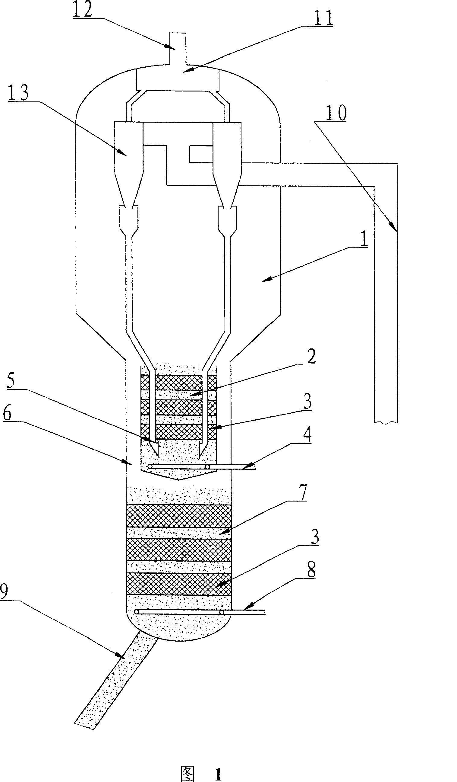
[0024] Embodiment 1: As shown in FIG. 1 , the oil gas and ungenerated catalyst after the reaction from the riser reactor 10 (part) enter into the cyclone separator 13 to preliminarily separate the oil gas and the ungenerated catalyst. After the oil and gas from different cyclone separators are collected into the gas collection chamber 11 of the settler, they enter the subsequent fractionation system through the pipeline 12 for subsequent separation of products. The spent catalyst separated by the cyclone separator 13 enters the bottom of the first stripping section 2 through the dipleg of the cyclone separator, and the stripping steam is distributed in the first stripping section 2 as uniformly as possible through the distributor 4 . Under the action of the stripping steam, the catalyst flows from the bottom of the first stripping section 2 through the multi-layer stripping packing 3 to the top of the stripping section, and overflows through the top edge of the stripping sectio...

Embodiment approach 2

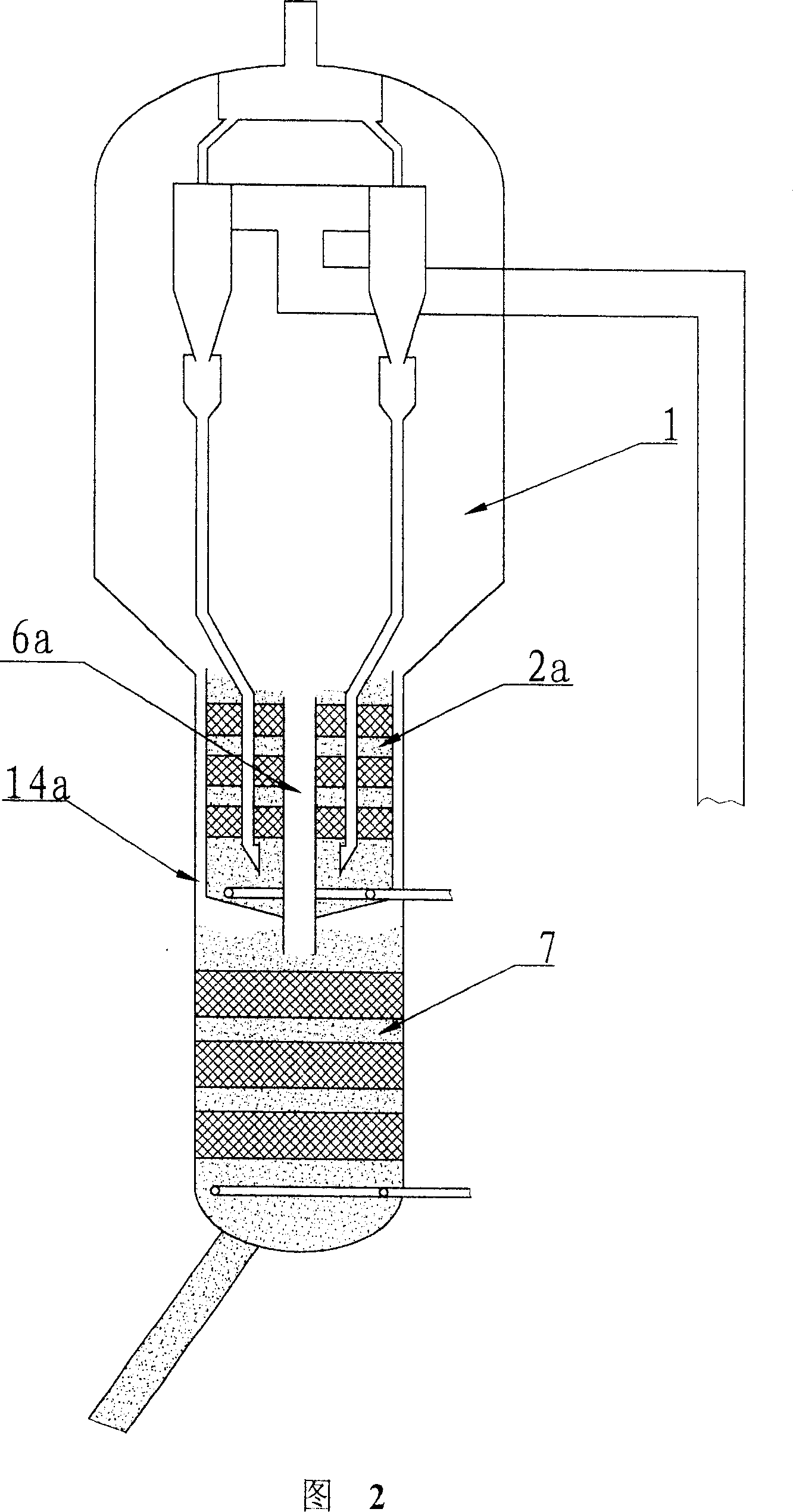
[0031] Embodiment two: as shown in Figure 2, this stripper comprises two stripper sections, and it differs from the stripper shown in Figure 1 in that: the catalyst that overflows through the first stripper section 2a is lowered by the center The feed pipe 6a enters the second stripping section 7, and the oil gas and stripping steam stripped from the second stripping section enters the dilute phase space of the settler 1 along the annular passage 14a. For realizing this purpose, the top outside edge of the first stripping section 2a will be 50-400mm higher than the top of the center lower feed pipe 6a, so just can guarantee that catalyst enters in the second stripping section from the center lower feed pipe, and Can not enter in the annular passage 14a that lifts up. Here the cross-sectional area of ​​the central feeding pipe accounts for 5-20% of the stripper cross-sectional area, and the cross-sectional area of ​​the annular channel accounts for 0.5-10% of the stripping cros...

Embodiment approach 3

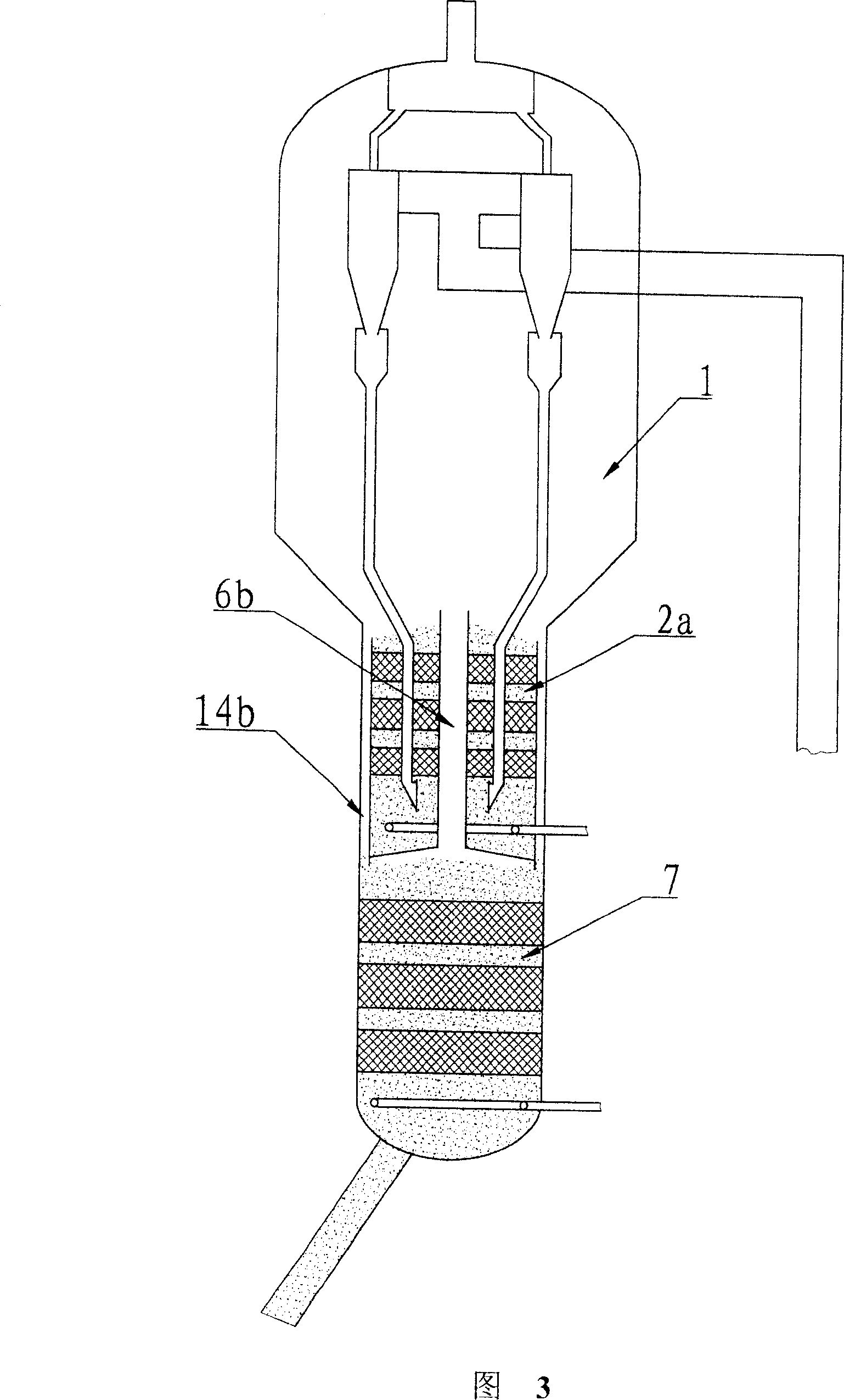
[0032] Embodiment three: as shown in Figure 3, the difference between this stripping method and the method shown in Figure 2 is: the catalyst that the first stripping section 2b overflows is overflowed by the top outside side wall of this stripping section The oil gas and stripping steam stripped from the second stripping section enter the dilute phase space of the settler 1 from the central riser 6b. For realizing this purpose, first stripping section 2b top outer edge will be 50-400mm lower than center gas riser 6b top, like this just can guarantee that catalyst enters in the second stripping section from the annular feeding channel 14b of side wall, And unlikely to enter in the central riser pipe. Here the cross-sectional area of ​​the annular passage 14b accounts for 5-20% of the stripper cross-sectional area, and the bottom of the annular passage 14b will extend to the top of the second stripping section, and the cross-sectional area of ​​the central air riser 6b accounts...


PUM

PropertyMeasurementUnit
heightaaaaaaaaaa
porosityaaaaaaaaaa
porosityaaaaaaaaaa

Abstract

This invention relates to catalyze multiple section stripper method, which comprises the following steps: transporting the stripper catalyze agent flowing freely form top to down to the top stripper section bottom in the stripper with more than two sections of stripper to remove the mixed gas or liquid materials; the catalyze flowing to the top and then to the downside stripper section; repeating the above steps in the down stripper section to the down the stripper section; in the down stripper section, the catalyze flowing to the bottom of the stripper section from top to down for exhausting the catalyze gas outside stripper; extracting the above materials together with medium gas channel outside the stripper.

Description

technical field [0001] The invention relates to a catalyst stripping method in the catalytic conversion process of petroleum hydrocarbons, more specifically, a catalyst multi-stage stripping method. Background technique [0002] Fluid Catalytic Cracking (FCC) is an important secondary processing process in the petroleum refining industry, which uses heavy feedstock oil to produce light oil products such as gasoline, diesel, and liquefied petroleum gas. The main steps are as follows. The hydrocarbon raw material is contacted with the hot regenerated catalyst in the riser, and the catalytic cracking reaction is carried out at 450 ° C ~ 550 ° C; The cyclone separator separates the raw catalyst and enters the stripper, and the oil and gas enters the subsequent product separation system. The raw catalyst is in countercurrent contact with water vapor in the stripper, and after removing the entrained hydrocarbons, it enters the regenerator for coke regeneration to restore the acti...

Claims


Application Information

Patent Timeline
Patent Type & Authority Patents(China)
IPC IPC(8): B01J38/06C10G11/18B01J8/18
Inventor 张永民侯栓弟李松年龙军张占柱张久顺武雪峰何峻
Owner CHINA PETROLEUM & CHEM CORP
Why Eureka
Try Eureka