Optical fibre Bragg grating sensing demodulating equipment and demodulating method thereof

A technology of chirped fiber gratings and optical fibers, applied in the field of demodulation devices for fiber Bragg grating sensing, can solve problems such as expensive and difficult to measure dynamic strain, achieve device cost reduction, change measurement sensitivity and measurement range, and optical path loss Falling effect

Inactive Publication Date: 2008-05-14
TIANJIN UNIV
View PDF6 Cites 1 Cited by
  • Summary
  • Abstract
  • Description
  • Claims
  • Application Information

AI Technical Summary

Problems solved by technology

[0016] With the maturity of the fiber Bragg grating sensor production technology, the price of the fiber Bragg grating sensor has dropped significantly, and the fiber Bragg grating demodulation device currently on the market is mainly based on the fiber Fa-Per filter, which is expensive and difficult to measure dynamic strain. Barriers to the popularization and development of sensing technology in fields such as oil well temperature, pressure and structural health monitoring

Method used


Image

  • Optical fibre Bragg grating sensing demodulating equipment and demodulating method thereof
  • Optical fibre Bragg grating sensing demodulating equipment and demodulating method thereof
  • Optical fibre Bragg grating sensing demodulating equipment and demodulating method thereof

Examples


Embodiment 1

[0037] Embodiment 1: demodulation device

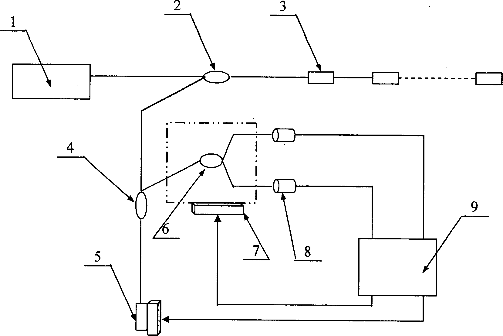
[0038] like figure 1 As shown, the optical fiber Bragg grating sensing demodulation device includes a broadband light source 1, the light of the broadband light source reaches the fiber Bragg grating sensor array 3 to be tested through the first coupler 2, and the reflected light passes through the first coupler 2 and the second coupler 4 to the chirped fiber grating 5, after the chirped fiber grating is adjusted, the chirped fiber grating reflects the signal of the fiber Bragg grating in its reflection spectrum back to the second coupler and reaches the fiber-based fused tapered device The linear filter 6, the output optical power at both ends of the optical fiber fusion tapered device is converted into an electrical signal by a pair of detectors 8, and sent to the signal processing and tuning control system 9 for collection and processing, and the signal processing and tuning control system are driven separately at the same time Th...

Embodiment 2

[0039] Embodiment 2: demodulation method

[0040] The demodulation process of the above-mentioned demodulation device is as follows:

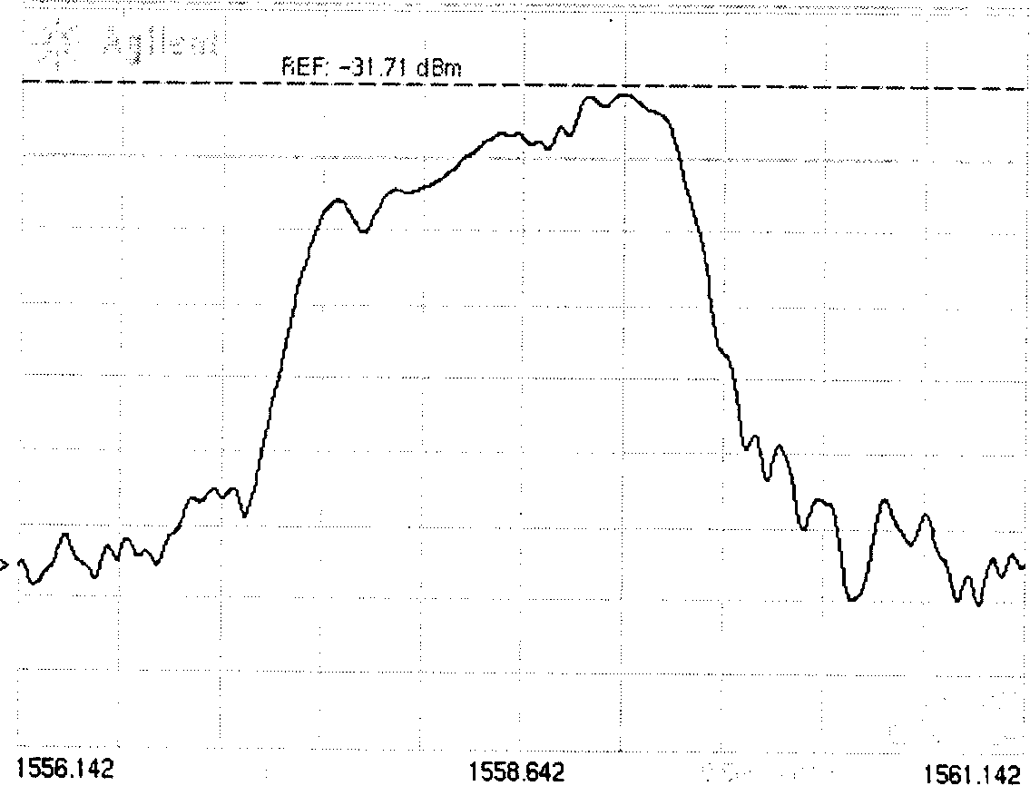
[0041] The light of the broadband light source 1 reaches the optical fiber Brgagg grating sensor array 3 to be tested through the first coupler 2, and the reflected light passes through the first coupler 2 and the second coupler 4 to the chirped fiber grating 5 place (the chirped fiber grating with the adjusting device The chirped fiber grating 5 is used to realize the selection of the fiber Bragg grating, and its reflection spectrum shows the figure 2 ), adjust the chirped fiber grating so that the center wavelength of its reflection spectrum moves to the vicinity of the center wavelength of the fiber Bragg grating to be detected, and the chirped fiber grating reflects the signal of the fiber Bragg grating in its reflection spectrum back to the second coupling and reach the linear filter based on the optical fiber fusion tapered device, the ...

Embodiment 3

[0049] Embodiment 3: Signal processing and tuning control system

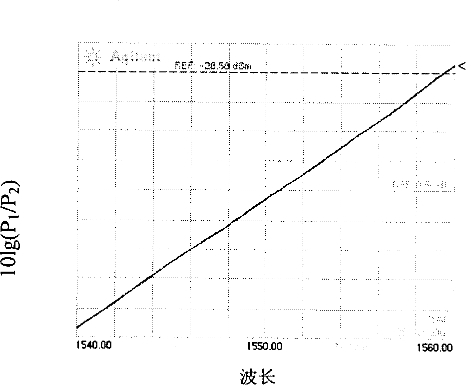
[0050] The structure of the signal processing and tuning control system is as follows: Figure 4 As shown, 10 and 11 are preamplifier circuits (see the connection circuit Figure 5 ), 12 and 13 are switches, and 14 and 15 are band-pass filter circuits (see the connection circuit Image 6 ), 16 and 17 are phase-sensitive detectors (see the connection circuit Figure 7 ), 18 and 19 are low-pass filter circuits, 20 is a logarithmic division circuit, 21 is a programmable amplifier circuit, 22 is a driver circuit for a linear filter regulator, 23 is a driver circuit for a chirped fiber grating regulator, and 24 is a The modulation signal generation circuit of the external modulator (see the connection circuit Figure 8 ), 25 is a man-machine interface circuit, 26 is a single-chip signal processing circuit, and 27 is a liquid crystal display circuit.

[0051] After the light intensity signal is converted into an ...


PUM


Abstract

This invention relates to fiber Bragg grating sensor modulation device and its method, which comprises the following steps: wide band source goes through first coupler to achieve fiber Bragg grating sensor array; the reflection light goes through first and second couplers to chirp fiber grating modulating and to reflect the signals into second coupler to achieve the linear filer based on fiber melt taper parts through one pair of detectors into electrical signal for processing and tuning control system for collection and process.

Description

【Technical field】: [0001] The invention relates to various optical fiber sensing fields based on fiber Bragg gratings, in particular to a demodulation device and a demodulation method for fiber Bragg grating sensing. 【Background technique】: [0002] The Fiber Bragg Grating (FBG) sensor is currently the most widely used fiber Bragg grating sensor. In the entire length of the fiber Bragg grating, the period and refractive index are uniform, and the Bragg resonance reflection wavelength: [0003] lambda B =2nΛ(1-1) [0004] In the formula, Λ is the grating period, and n is the effective refractive index of the fiber core. External disturbances to be measured, such as strain, will cause changes in the refractive index and period of the FBG, thereby causing the Bragg reflection wavelength of the FBG to shift. The change information to be measured can be obtained by measuring the drift of the wavelength. [0005] An extremely important link in fiber Bragg grating sensing is th...

Claims


Application Information

Patent Timeline
Patent Type & Authority Patents(China)
IPC IPC(8): G02F2/00G02B6/26
Inventor 江俊峰刘铁根王云新张以谟
Owner TIANJIN UNIV
Why Eureka
Try Eureka