Quick forming method by adoption of projection technique
A projection technology, a fast technology, applied in the field of manufacturing, can solve the problems of low automation, poor molding precision, high cost of use, etc., and achieve the effect of large selection range, easy control and adjustment, and convenient control
- Summary
- Abstract
- Description
- Claims
- Application Information
AI Technical Summary
Problems solved by technology
Method used
Image
Examples
Embodiment 1
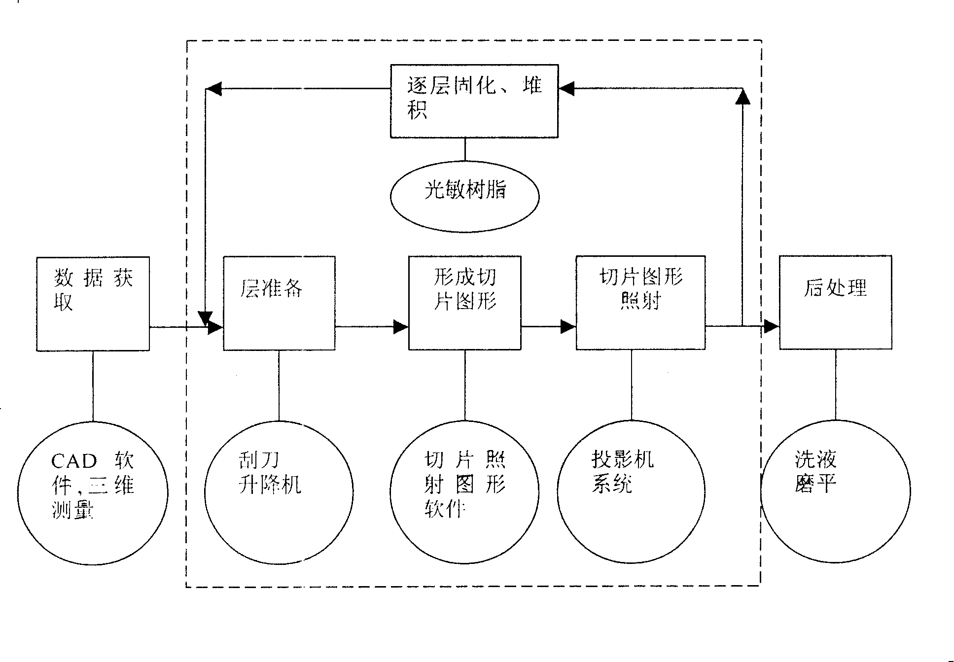
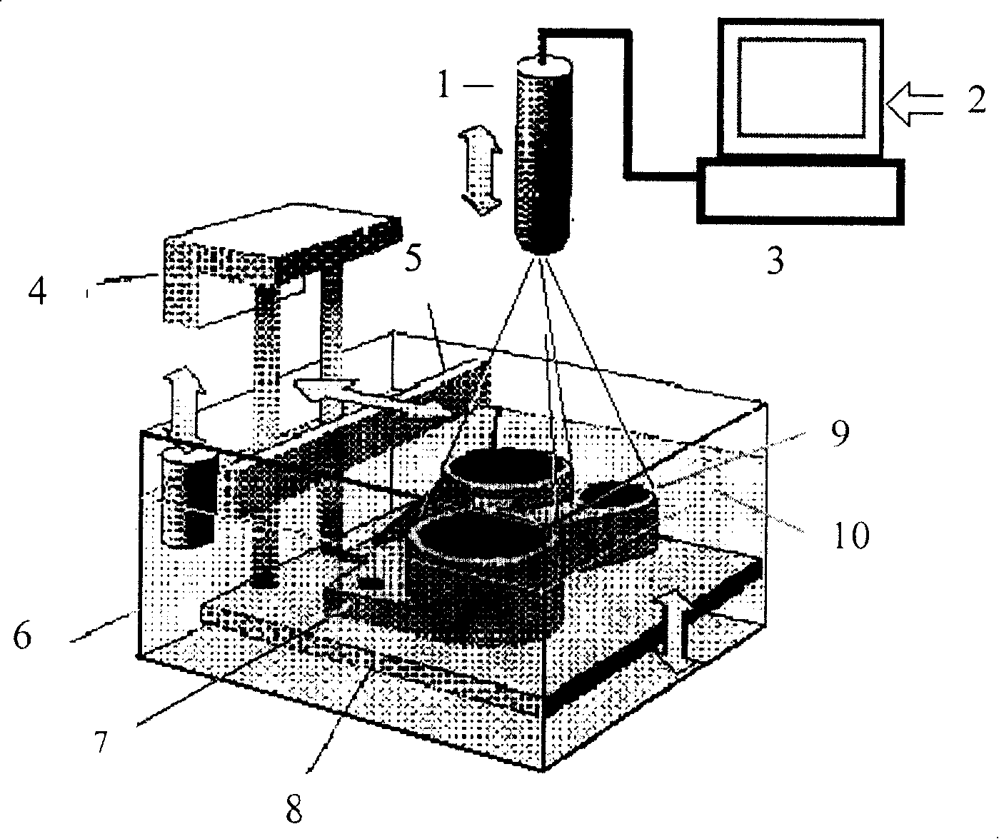
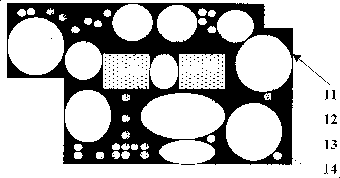
[0062] The structure of the rapid prototyping machine is as figure 2 As shown, 50kg DuPont SOMOS 6100 photosensitive curing resin is loaded into the liquid tank 6, and the TGC-1 control software is loaded into the computer 3 (the flow of the TGC-1 control software is as follows: Figure 4 Shown), the digital three-dimensional model 2 of the object can be displayed on the computer display; the projector 1 connected to the computer is located above the tray 8. The photosensitive resin on the tray is provided by the liquid tank 6 to maintain the photosensitive resin liquid on the tray 6. The distance between the surface 10 and the projector is constant, so that the size of the projected graphic 9 on the liquid surface of the photosensitive resin remains the same. The lifting of the tray 8 is adjusted by the elevator 4; a horizontally reciprocating scraper 5 is installed on the liquid tank 6 to ensure The stability of the liquid surface position of the thin layer of photosensitive res...
Embodiment 2
[0082] The structure of the rapid prototyping machine and the rapid prototyping method are as in Example 1.
[0083] Projector parameters: three LCD transmission methods, resolution 800×600, light source 500W, iodine tungsten lamp, wavelength 40nm ~ 800nm.
[0084] Control parameters: Irradiation area: 150mm×150mm
[0085] Forming shape: cube
[0086] Forming size: 100mm×100mm×100mm
[0087] Support size: 100mm×100mm×10mm
[0088] The thickness of each layer in the forming process of the molded object: 0.1mm
[0089] Irradiation times: Support 50 times
[0090] The total number of irradiation times of the forming entity: 10000 times
[0091] Each irradiation time: 1.0 second
[0092] Test result: Forming time: 270 minutes (including the leveling action of layer preparation and the time required to switch the irradiation pattern)
[0093] Physical size: 99.66mm×9.66mm×99.85mm
[0094] Forming accuracy: X axis: 0.34%
[0095] Y axis: 0.34%
[0096] Z axis: 0.15%
[0097] Note: The s...
Embodiment 3
[0099] The structure of the rapid prototyping machine and the rapid prototyping method are as in Example 1.
[0100] Projector parameters: three LCD reflection methods, resolution 1024×768, light source 50W, UHP lamp, wavelength 40nm ~ 800nm.
[0101] Control parameters: Irradiation area: 120mm×120mm
[0102] Forming shape: cube
[0103] Forming size: 100mm×100mm×100mm
[0104] Support size: 100mm×100mm×10mm
[0105] The thickness of each layer in the forming process of the molded object: 0.1mm
[0106] Irradiation times: Support 50 times
[0107] The total number of irradiation times of the forming entity: 10000 times
[0108] Each irradiation time: 1.0 second
[0109] Test result: Forming time: 386 minutes (including the time required for the leveling action of the layer preparation and the switching of the irradiation pattern)
[0110] Physical size: 99.66mm×9.66mm×99.85mm
[0111] Forming accuracy: X axis: 0.21%
[0112] Y axis: 0.21%
[0113] Z axis: 0.13%.
PUM
 Abstract
Description
Claims
Application Information
 - R&D
- Intellectual Property
- Life Sciences
- Materials
- Tech Scout
- Unparalleled Data Quality
- Higher Quality Content
- 60% Fewer Hallucinations
Browse by: Latest US Patents, China's latest patents, Technical Efficacy Thesaurus, Application Domain, Technology Topic, Popular Technical Reports.
© 2025 PatSnap. All rights reserved.Legal|Privacy policy|Modern Slavery Act Transparency Statement|Sitemap|About US| Contact US: help@patsnap.com


