Phase locking method of using outer cavity coherent of semiconductor laser coupled to optical fiber

A fiber coupling and semiconductor technology, applied in the field of external cavity coherent phase locking, can solve the problems of complex structure, inconvenient adjustment, large loss, etc., and achieve the effect of compact and simple structure, reduced optical loss, and reduced cost

Inactive Publication Date: 2008-08-06
BEIJING UNIV OF TECH
View PDF8 Cites 0 Cited by
  • Summary
  • Abstract
  • Description
  • Claims
  • Application Information

AI Technical Summary

Problems solved by technology

[0004] In order to solve the problems of complex structure, large loss, inconvenient adjustment, and high cost in the background technology of active phase control method, spatial filtering method and Talbot external cavity method, the present invention provides an external laser diode coupled with optical fiber. Cavity coherent phase-locked method, this method can obtain semiconductor coherent phase-locked laser output with narrow linewidth and high peak power

Method used


Image

  • Phase locking method of using outer cavity coherent of semiconductor laser coupled to optical fiber
  • Phase locking method of using outer cavity coherent of semiconductor laser coupled to optical fiber

Examples


Embodiment 1

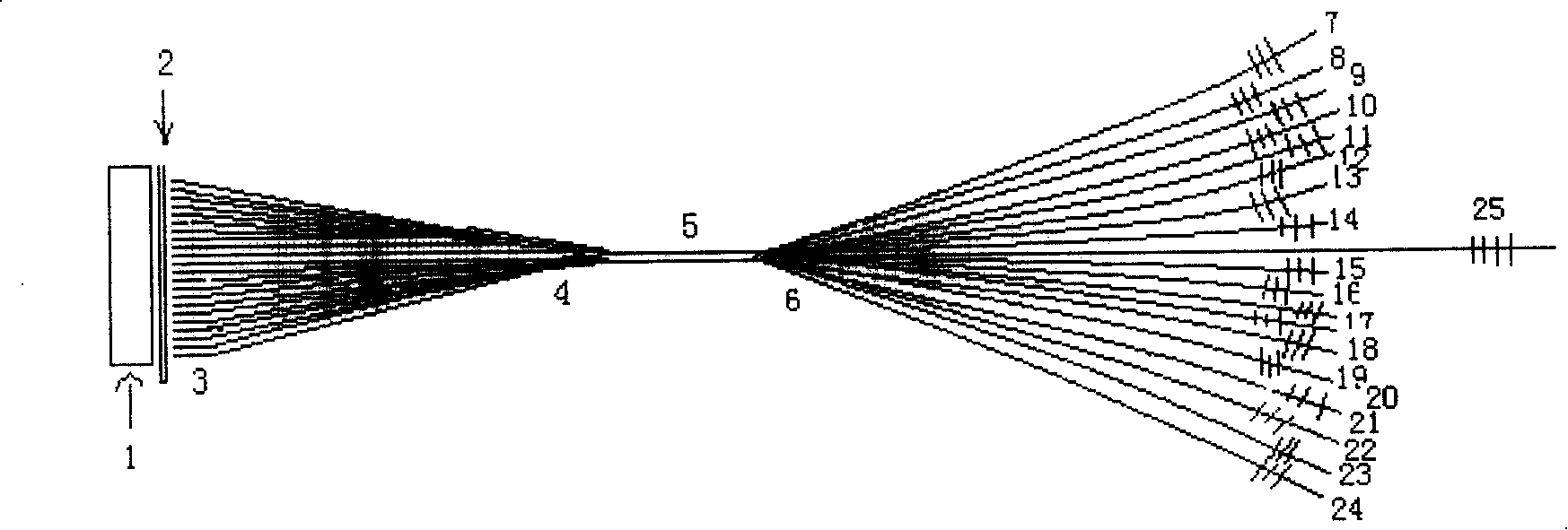
[0014] Example 1: figure 1 Shown is a first embodiment of the invention. Select a linear array of semiconductor lasers, wherein 19 light-emitting units are selected, and a focusing collimating lens 2 is installed at about 0.5mm in front of the light-emitting surface of the semiconductor laser 1, and the other side of the focusing collimating lens 2 is close to the focusing collimating lens. The output surface of the straight lens is one-to-one parallel to the light-emitting unit, and 19 optical fibers are bonded to form an optical fiber array 3, and then the other end of the optical fiber array 3 composed of 19 optical fibers pasted and coupled is bundled into an optical fiber bundle. The beam is directly fused into a large-diameter multi-film optical fiber 5, and the other end of the large-diameter multi-film optical fiber 5 is also fused with a 1×(18+1) multi-film optical fiber beam splitter 6, of which 18 output ends It is the auxiliary output terminal, and one is the main...

Embodiment 2

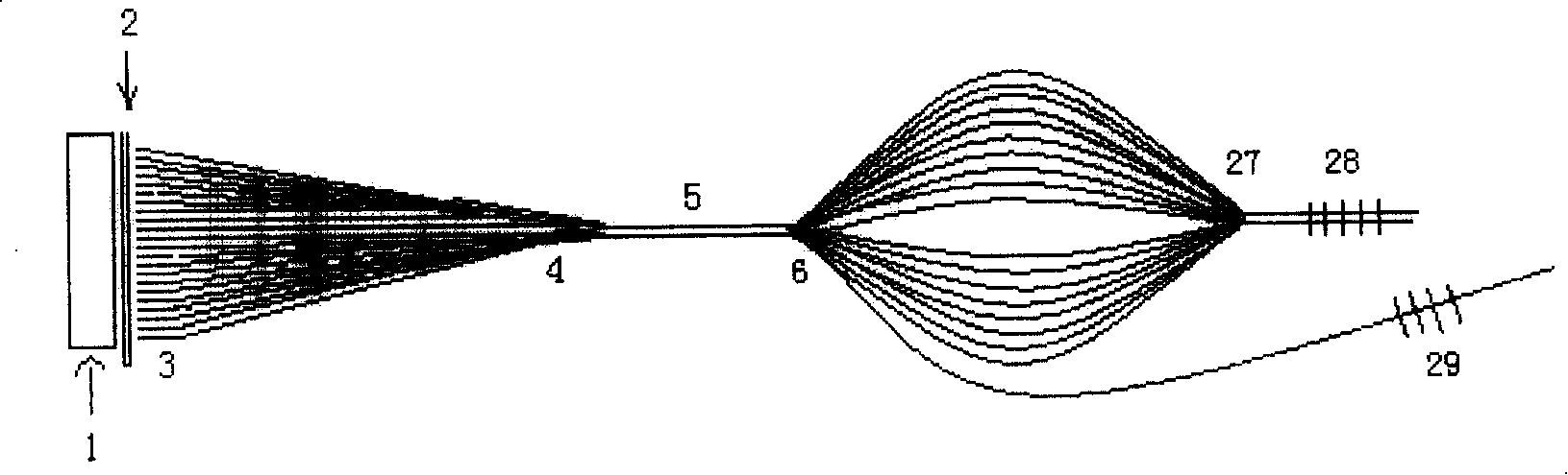
[0015] Example 2: figure 2 Shown is a second embodiment of the invention. Select a semiconductor laser linear array 1, wherein 19 light-emitting units are selected, and a focusing collimating lens 2 is installed at about 0.5mm in front of the light-emitting surface of the semiconductor laser 1, and the other side of the focusing collimating lens 2 is close to the focusing The output surface of the collimator lens is one-to-one parallel to the light-emitting unit, and 19 optical fibers are bonded to form an optical fiber array 3, and then the other end of the optical fiber array 3 composed of pasted and coupled 19 optical fibers is bundled into an optical fiber bundle. The fiber bundle is directly fused into a large-diameter multi-film optical fiber 5, and the other end of the large-diameter multi-film optical fiber 5 is also fused with a 1×(18+1) multi-film optical fiber beam splitter 6, of which 18 output The end is the auxiliary output end, and one is the main output end. ...


PUM


Abstract

An external cavity coherent phase-locking method of semiconductor laser used to couple optical fiber includes setting focus collimating lens in front of semiconductor laser array, sticking optical fiber on each lightening unit set at another side of said lens and corresponded to said laser array, forming stuck optical fiber to be an optical fiber array, welding said fiber array in a multimode optical fiber and welding N numbers of optical fibers on another end of multimode optical fiber then welding optical fiber grating used as external cavity reflector in position at the same length on N numbers of optical fibers.

Description

technical field [0001] The invention relates to an external-cavity coherent phase-locking method using a fiber-coupled semiconductor laser, and belongs to the technical field of laser multi-beam shaping, coupling and coherent light mode locking. Background technique [0002] Since each light-emitting unit of a high-power semiconductor laser is photoelectrically isolated, the output radiation is spatially incoherent, the light field distribution is uneven, and the beam quality is poor. If the light emitted by several lasers with the same parameters is superimposed in a common resonator, the phase auto-locking process will occur to form coherent laser oscillation in the resonator. External cavity phase-locked coherent technology is the technology to achieve coherent laser oscillation. It forms a new resonant cavity outside the semiconductor laser to lock the phase of each laser unit, so as to obtain a near-diffraction coherent output. This technology improves the beam quality...

Claims


Application Information

Patent Timeline
Patent Type & Authority Patents(China)
IPC IPC(8): G02B6/42G02B6/34G02B6/26
Inventor 张亮王智勇左铁钏
Owner BEIJING UNIV OF TECH
Why Eureka
Try Eureka