Method for manufacturing stainless steel tail gas pipe of car, and automatic cutter for cutting stainless steel pipe
A technology of automobile exhaust and manufacturing method, applied in the direction of engine components, mechanical equipment, etc., can solve the problems of uneven austenitization, low production efficiency, poor finish, etc., and achieve uniform austenitization, good cutting quality, and cutting high efficiency effect
- Summary
- Abstract
- Description
- Claims
- Application Information
AI Technical Summary
Problems solved by technology
Method used
Image
Examples
Embodiment 1
[0015] The manufacturing method of the stainless steel automobile exhaust pipe is as follows:
[0016] 1. Raw material inspection
[0017] Take the steel strip, check the chemical composition of the steel strip, the nominal size, and the smooth surface with or without oil.
[0018] 2. Strip cutting
[0019] Lift the strip and clamp the strip on the chuck of the disc shearing machine, feed the strip into the cutting edge, and gradually adjust the speed to medium speed for normal operation and cut.
[0020] 3. Welded pipe
[0021] Put the strip on the unwinding machine, scrub the surface of the material with vinyl chloride to make the surface of the material clean; press one end of the strip into the forming roller, so that the strip is uniformly formed into a circular tube in the forming roller, and the welding speed is 6m / min, current 75A or welding speed 10m / min, current 100A or welding speed 8m / min, current 85A;
[0022] 4. Wall reduction and diameter reduction
[0023...
Embodiment 2
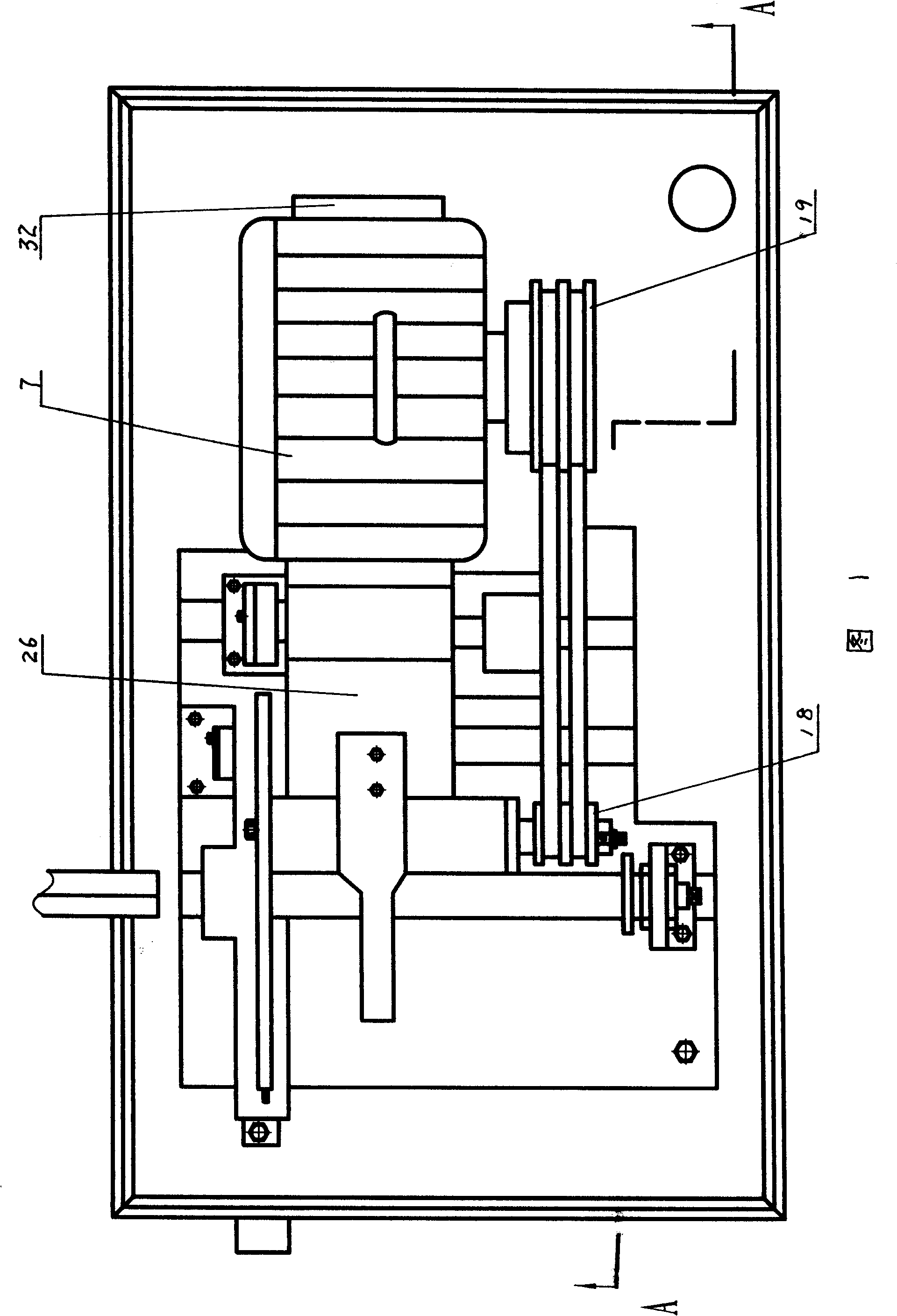
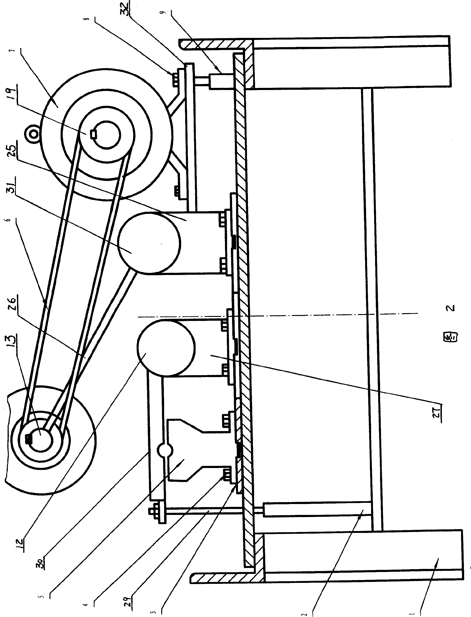
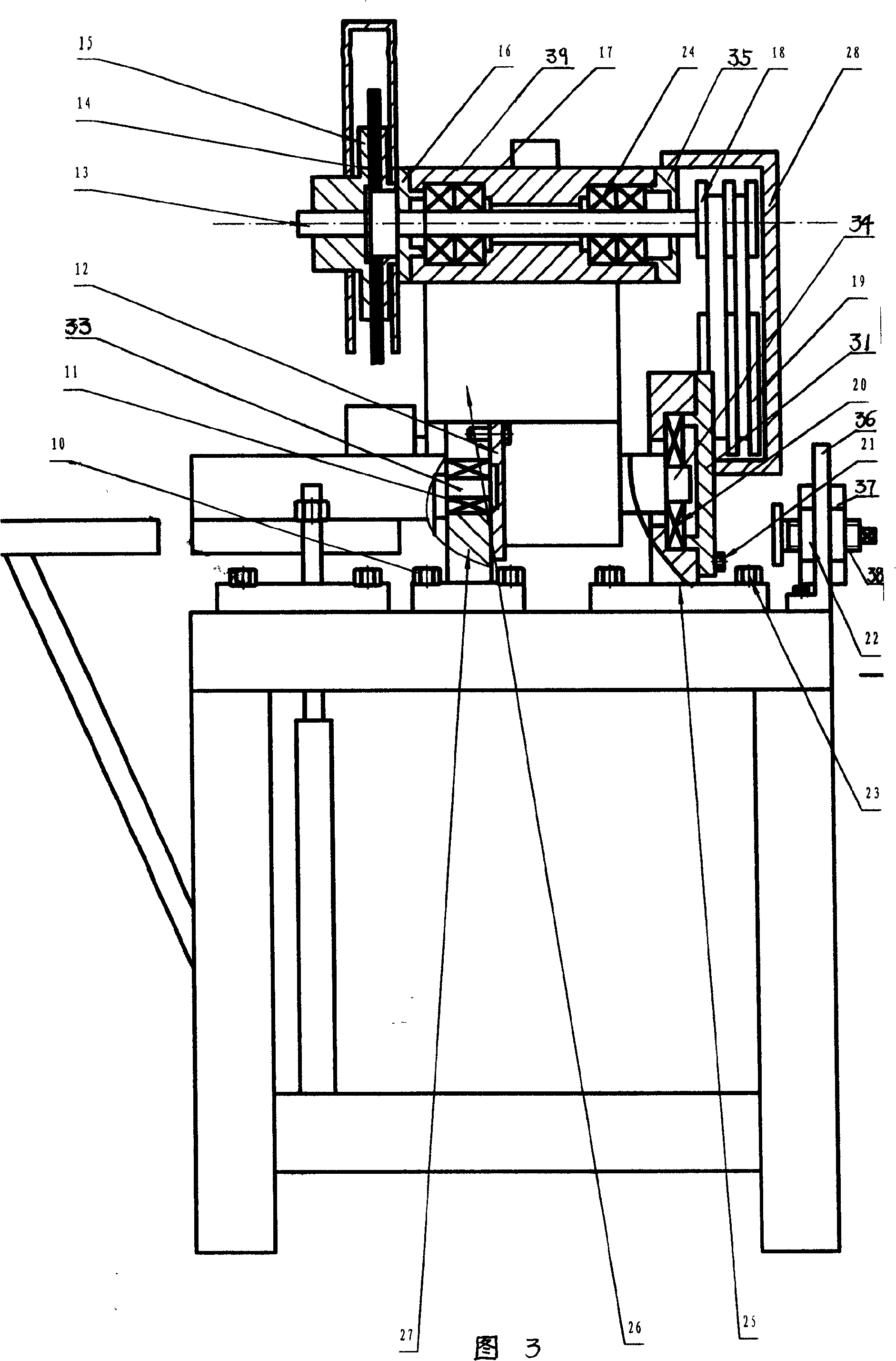
[0044]As shown in the figure, the stainless steel pipe automatic cutting machine has a frame 1, a base plate 3 is installed on the frame 1, a clamping body 5 is installed on the base plate 3 through bolts 4, and a clamping body 5 is installed on the base plate 1 through bolts 10. There is a small bearing seat 27, a pressure cover 12 is installed at the end of the small bearing seat 27, a radial ball bearing 11 is installed in the small bearing seat 27, a pressure plate main shaft 33 is installed in the radial ball bearing 11, and the pressure plate main shaft 33 is connected with a The pressure plate 30, the pressure plate 30 corresponds to the position of the clamping body 5, and a pressure plate lifting cylinder 2 is provided on the frame 1 at the position below the end of the pressure plate 30, and the cylinder rod 29 of the pressure plate lifting cylinder 2 is connected with the pressure plate 30. , on the frame 1, an intermediate bearing seat 25 is provided on the side of ...
PUM
 Abstract
Description
Claims
Application Information
 - R&D
- Intellectual Property
- Life Sciences
- Materials
- Tech Scout
- Unparalleled Data Quality
- Higher Quality Content
- 60% Fewer Hallucinations
Browse by: Latest US Patents, China's latest patents, Technical Efficacy Thesaurus, Application Domain, Technology Topic, Popular Technical Reports.
© 2025 PatSnap. All rights reserved.Legal|Privacy policy|Modern Slavery Act Transparency Statement|Sitemap|About US| Contact US: help@patsnap.com


