
Power driven and braking equipment of pressing machine driven by servomotor directly

A servo motor and power transmission technology, applied in the field of presses, can solve the problems of noise pollution, high maintenance costs, and excessive noise of operators and the surrounding environment, and achieve the effects of good braking performance, saving maintenance costs, and low vibration.

Inactive Publication Date: 2008-10-01
JIANGSU XUZHOU METALFORMING MACHINE GROUP
View PDF5 Cites 0 Cited by
  • Summary
  • Abstract
  • Description
  • Claims
  • Application Information

AI Technical Summary

Problems solved by technology

The brake system of the currently used press adopts a pneumatic brake, which is composed of electromagnetic clutches, friction plates, hydraulic valves and other components.

Method used


Image

  • Power driven and braking equipment of pressing machine driven by servomotor directly
  • Power driven and braking equipment of pressing machine driven by servomotor directly

Examples


Embodiment Construction

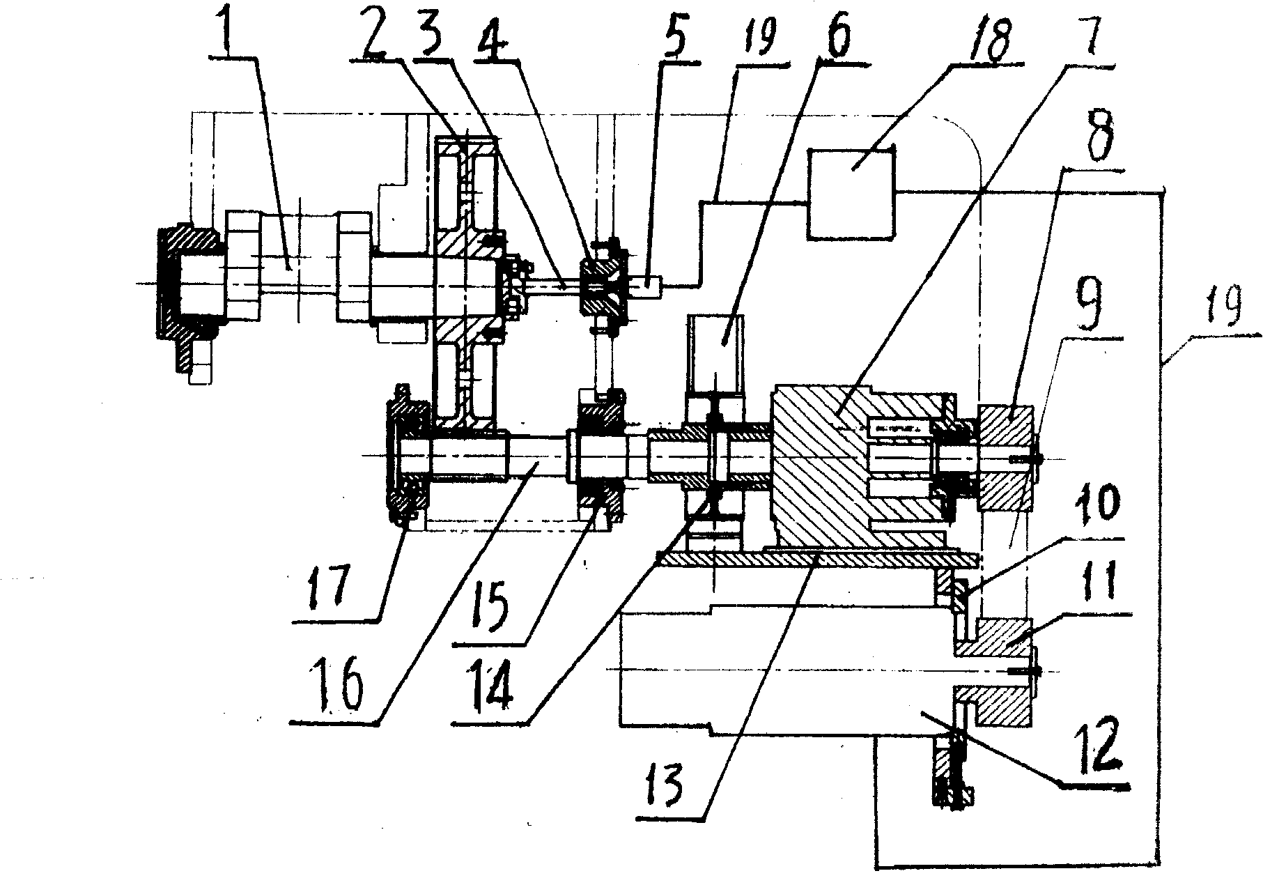
[0012] Such as figure 1 As shown, the servo motor 12 installed in the lower part of the fuselage 13 transmits power to the reduction box 7 installed on the fuselage 13 through the pulley 11, the pulley 8 and the belt 9. After deceleration, its output shaft passes through the coupling with the brake 6. The shaft device 14 transmits the power to the gear shaft 16. The gear shaft 16 is coaxially installed on the machine body through the bearing housings 15, 17. The gear shaft 16 meshes with the gear 2 to achieve the second-stage deceleration and then drives the crankshaft 1 to rotate, and the crankshaft drives the sliding shaft. The block moves up and down to complete the punching function. The end of the crankshaft 1 coaxially fixes the encoder output shaft 3, and is connected to the resolver 5 in the resolver base 4 installed on the fuselage. The resolver 5 inputs the rotation signal of the crankshaft to the encoder 18 through the signal line 19, After being processed by the encod...


PUM


Abstract

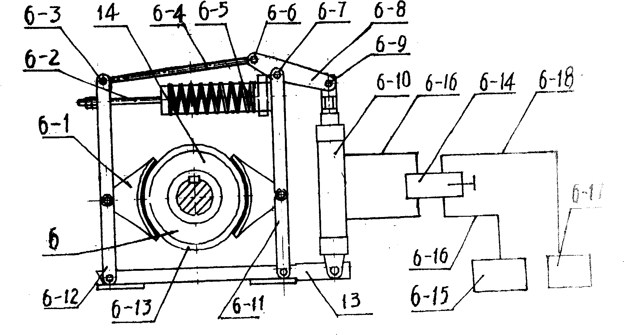
A power transmitting and braking apparatus for a press driven directly by servo motor is disclosed. The gear and the slide block of crankshaft are driven by a servo motor via speed reducer and gear axle. The encoding output axle fixed to external end of crankshaft is synchronous with a rotary transformer. The rotation speed signal of crankshaft is sent to a programming device by said rotary transformer, where it is processed and then output to servo motor for controlling the servo motor. Its braking unit has an improved structure consisting of braking wheel, spring, braking cylinder, crank-connecting rod mechanism and drum brake, and features high response speed and low noise.

Description

Technical field [0001] The invention relates to a press, in particular to a power transmission and braking device in which a servo motor directly drives the press. Background technique [0002] At present, the working power motor of the ordinary crankshaft press has been running continuously after it is turned on. A huge flywheel is installed outside the fuselage. The reduction box drives the flywheel to rotate. The flywheel rotates inertia to drive the crankshaft to rotate. The block moves up and down to realize the punching function. The idling of the motor and flywheel produces a large amount of non-functional consumption. The brake system of the currently used press adopts pneumatic brake, which is composed of electromagnetic clutch, friction plate, hydraulic valve and other components. The structure is complicated, the maintenance cost is high, the noise is seriously exceeded, and it brings great noise pollution to the operators and the surrounding environment. . Summary of...

Claims


Application Information

Patent Timeline
Patent Type & Authority Patents(China)
IPC IPC(8): B30B15/14B30B15/10
Inventor 王晓东姚立敏闫长海薛杨李黎明夏伟
Owner JIANGSU XUZHOU METALFORMING MACHINE GROUP
Learn More