Check patentability & draft patents in minutes with Patsnap Eureka AI!

Device and method for wafer alignment with reduced tilt sensitivity

A technology for aligning devices and diffracting light beams, which is applied in the directions of optomechanical equipment, microlithography exposure equipment, transportation and packaging, etc., can solve problems such as complex costs, and achieve the effect of reducing sensitivity

Inactive Publication Date: 2009-01-14
ASML NETHERLANDS BV
View PDF17 Cites 0 Cited by
  • Summary
  • Abstract
  • Description
  • Claims
  • Application Information

AI Technical Summary

Problems solved by technology

[0021] In order to improve wafer alignment with reduced tilt sensitivity in lithographic apparatus, the prior art is disclosed in US 2001 / 0008273 A1 concerning an Abbe arm calibration system for Kepler telescopes, which system is rather complicated and expensive

Method used


Image

  • Device and method for wafer alignment with reduced tilt sensitivity
  • Device and method for wafer alignment with reduced tilt sensitivity
  • Device and method for wafer alignment with reduced tilt sensitivity

Examples


Embodiment Construction

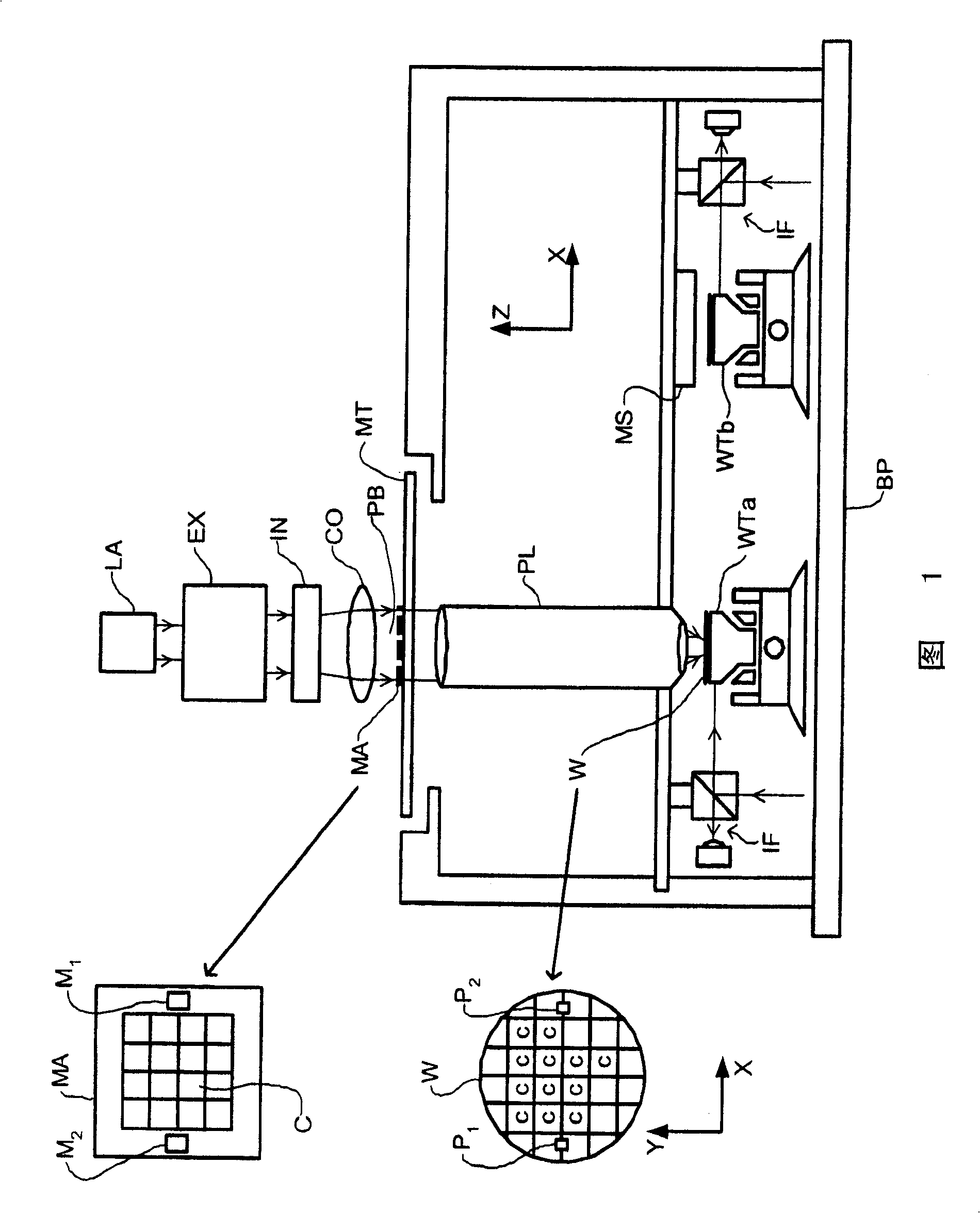
[0060] Figure 1 schematically depicts a lithographic projection apparatus 1 of a specific embodiment of the present invention. The device is of the type with two substrate tables WTa and WTb, comprising:

[0061] - A radiation system Ex, IL providing a radiation projection beam PB (eg UV radiation). In this particular example, the radiation system also includes a radiation source LA;

[0062] - a first stage (mask table) MT provided with a mask holder for holding a mask MA (eg reticle) and with a first positioning device for precise positioning of the mask relative to the object PL Device PM connection;

[0063] - second and third stages (substrate tables) WTa and WTb, each provided with a substrate holder for holding a substrate W (e.g. a resist-coated silicon wafer), and each connected to a respective stage position device (not shown), the second object stage is positioned under the projection system PL, and its stage positioning device is arranged to precisely position t...


PUM

PropertyMeasurementUnit
diameteraaaaaaaaaa

Abstract

A lithographic projection apparatus comprising: patterning means for, in use, patterning a projection beam according to a desired pattern as a patterning beam; a substrate table (WS) holding a substrate; a substrate alignment means (MS) for for detecting the position of the substrate relative to the patterning device; the substrate comprises at least one grating (MAR) having a diffractive length and being arranged, in use, to pass through an incident light beam ( IB; IB2) interaction over the diffraction length, producing at least one diffraction order of the constituent diffracted beams (DB1, DB2); said substrate alignment means (MS), comprising a A light source, and optics (1) for imaging said at least one diffraction order onto a sensor device (DET); said optics (1), comprising aperture means (TA) with apertures (PH1, PH2) at predetermined positions , so that said composed diffracted beams (DB1, DB2) pass; wherein each of said composed diffracted beams (DB1, DB2) has a diffracted beam diameter (BD1, BD2) at the level of said aperture (PH1, PH2), Said diffracted beam diameter (BD1, BD2) of each said constituent diffracted beam (DB1, DB2) is larger than said aperture (PH1, PH2) diameter.

Description

technical field [0001] The present invention relates to a lithographic projection apparatus including an apparatus for wafer alignment with reduced tilt sensitivity. The invention also relates to a method for wafer alignment with reduced tilt sensitivity. Background technique [0002] The present invention finds a preferred application in the field of lithographic projection apparatus comprising a radiation system for providing a radiant projection beam, a support structure for supporting a patterning device for patterning the projection beam according to a desired pattern, maintaining a substrate table of the substrate; and a projection system for projecting a patterned light beam onto a target area of ​​the substrate. [0003] The term "patterning device" as used herein should be construed broadly as a component capable of imparting a patterned cross-section to an incident beam of radiation, wherein the pattern corresponds to a pattern to be formed on a target portion of ...

Claims


Application Information

Patent Timeline
Patent Type & Authority Patents(China)
IPC IPC(8): G03F7/20G03F7/00G03F9/00H01L21/027
CPCG03F9/7049G03F9/7088G03F9/7034G03F9/7046B65H59/382B65H2403/7251
Inventor G·范德朱
Owner ASML NETHERLANDS BV
Features
  • R&D
  • Intellectual Property
  • Life Sciences
  • Materials
  • Tech Scout
  • Unparalleled Data Quality
  • Higher Quality Content
  • 60% Fewer Hallucinations
Learn More