Shaft kiln heat recovery method and device

A heat energy recovery and shaft kiln technology, applied in the field of cement building materials, can solve the problems of affecting the crushing particle size and the service life of equipment, increasing the labor intensity of workers, and harming the health of workers, etc., and achieves the effect of simple structure, increased thickness and reduced coal consumption.

Inactive Publication Date: 2009-01-28
缪建通
View PDF3 Cites 0 Cited by
  • Summary
  • Abstract
  • Description
  • Claims
  • Application Information

AI Technical Summary

Problems solved by technology

[0005] The temperature of the firing zone must be maintained during the calcination of the shaft kiln, otherwise the quality of the clinker will be affected, so the thickness of the wet material layer must be thickened to maintain the temperature in the kiln, so that the temperature of the kiln surface is low. The dew temperature will cause condensation on the bag, which is not conducive to ventilation and dust removal, causing equipment damage and economic losses, increasing the labor intensity of workers, and damaging the health of workers
[0006] Since the temperature of the clinker coming down from the kiln discharge pipe is as high as 300-500°C, after it is directly cooled in the grate cooler, the high-temperature gas generated can reach 400-600°C and directly enters the dust collector, which may burn the equipment in the dust collector ; Direct discharge is more harmful to the atmosphere and affects the working environment
[0007] After the clinker enters the clinker crusher, after extrusion and crushing, the temperature inside the block clinker is released, as well as the heat generated during crushing and extrusion, the cavity of the crusher is filled with high-temperature gas, and the wall of the crusher in a high-temperature environment The plates and hammer heads will be deformed due to continuous extrusion, which will seriously affect the crushing particle size and the service life of the equipment, causing serious equipment problems and economic losses

Method used


Image

  • Shaft kiln heat recovery method and device

Examples


Embodiment Construction

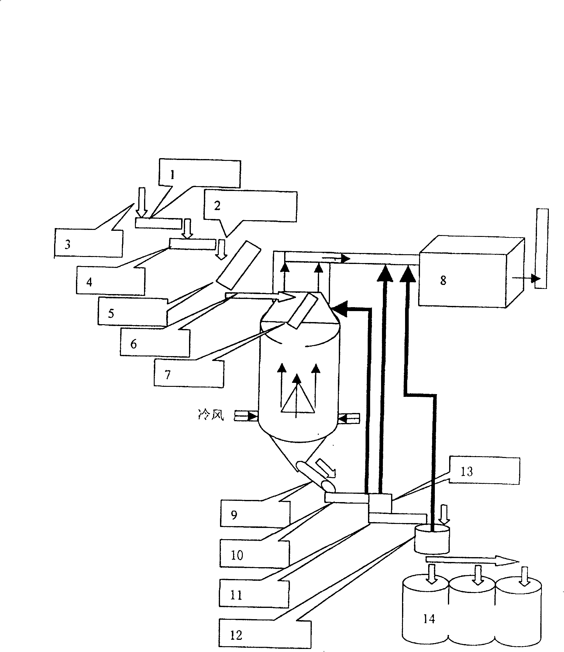
[0014] The exhaust gas from the grate cooler passes through the pipeline, enters the kiln surface and mixes the kiln surface flue gas, and then enters the dust collector; due to the high temperature of the flue gas, the bag is not easy to condense, which greatly prolongs the service life of the equipment and reduces the labor intensity of the workers. Since the flue gas entering the dust collector is mixed with the flue gas from the kiln and the exhaust gas from the grate cooler, the temperature of the flue gas from the kiln is allowed to be lower, so the preheating zone can be thickened, the thickness of the wet material layer can be increased, and the coal consumption can be reduced.

[0015] Due to the forced rapid cooling of the clinker in the grate cooler, the clinker breaks and disperses to produce a lot of fine ash and water vapor. After the clinker leaves the grate cooler and enters the dust collector,

[0016] It can enter the dust collector through the pipeline, which...


PUM


Abstract

The invention relates to the method and device of the shaft kiln heat recovery, the characterizes are the exhaust gas of the cooler passes through the pipelines into the kiln then mixes the gas to enter the filter; thickening the preheating zone, increasing the wet material thickness; the cooked materials come out of the cooler and enter the dust mask, through the heat recovery duct into the filter; the high temperature exhaust gas of the crusher cavity through the heat recovery duct, access to the wind tube of the filter; on the two heat recovery duct installs the temperature control diction which is controlled by the procedure controller and air valve. The invention advantages: simple, reliable operation, the high precision measurement of heat recovery automation control device. The operators will be monitored in operation room timely and accurately, realize the manpower monitoring to reduce the labor intensity, increase production, reduce the coal consumption. At the same time the production process is stabile, improves the quality of products, reduces the coal consumption about 10 percent, and the output of each production increased about 10 percent; reduces the labor intensity of the operator, protects the health of workers and so on advantages.

Description

technical field [0001] The invention relates to a method and a control system for recovering heat energy of a cement shaft kiln. The invention belongs to the technical field of cement building materials. Background technique [0002] The reduction of the heat consumption of the cement shaft kiln is a major difficulty in the cement production process. my country's cement industry consumes nearly 100 million tons of standard coal and 65 billion kWh of electricity every year, making it the second largest energy consumer after the metallurgical industry. Moreover, the average energy consumption of cement production in my country is much higher than the world's advanced level. Calculated by the comprehensive energy consumption per ton of clinker, the world's advanced level is 107kg standard coal, while my country's is 153.5kg standard coal, which is more than 50% higher. Shaft kiln cement consumes more energy. At present, the heat consumption of shaft kiln cement is relatively...

Claims


Application Information

Patent Timeline
Patent Type & Authority Patents(China)
IPC IPC(8): F27D17/00F27B1/10F27B1/26
Inventor 缪建通
Owner 缪建通
Why Eureka
Try Eureka