A reinforced method of guiding surfaces in guiding protection equipment of long thin embossing dies

A protective device, slender technology, applied in the direction of forming tools, furnace types, liquid chemical plating, etc., can solve the problems of insufficient strength, hardness, wear resistance, etc., achieve high price, save mold material costs, and guide the length of protection increased effect

Inactive Publication Date: 2009-03-04
SOUTH CHINA UNIV OF TECH
View PDF7 Cites 1 Cited by
  • Summary
  • Abstract
  • Description
  • Claims
  • Application Information

AI Technical Summary

Problems solved by technology

[0004] Another object of the present invention is to provide a method for strengthening the guide profile of the guide protection device of a precision slender punch. After the above-mentioned protective cover is manufactured with cheap tool steel instead of cemented carbide, the guide profile of the protective cover is chemically Composite plating strengthening can not only effectively solve the problem of insufficient strength, hardness and wear resistance of the protective sleeve made of cheap tool steel instead of cemented carbide, but also significantly reduce the adhesive wear between the protective sleeve and the punch, and Make the protective sleeve have the function of self-lubricating

Method used


Image

  • A reinforced method of guiding surfaces in guiding protection equipment of long thin embossing dies
  • A reinforced method of guiding surfaces in guiding protection equipment of long thin embossing dies

Examples


Embodiment 1

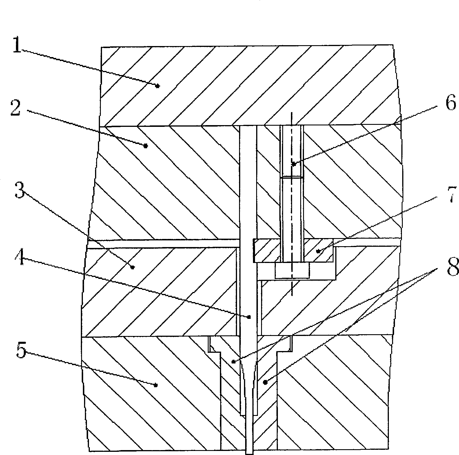
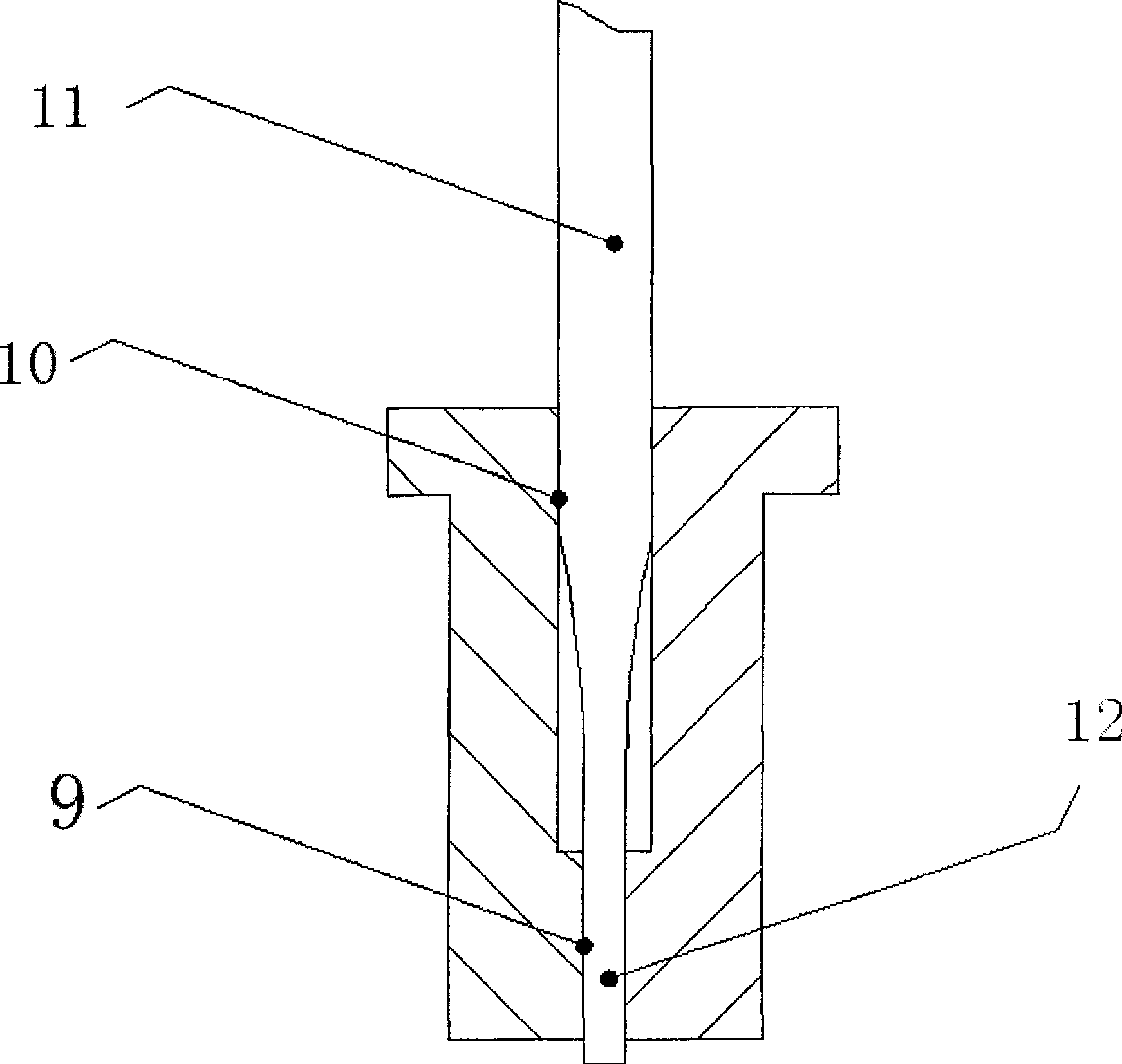
[0024] Such as figure 1 Shown is the structure of the slender punch double-guided protective cover, the punch fixed plate 2, the discharge backing plate 3, the slender punch 4, the discharge plate 5 and the double-guided protective cover 8 are located on the upper backing plate 1 One side; the elongated punch 4 is positioned in the punch fixing plate 2, and is clamped by the splint 7 and the screw A6; the upper backing plate 1 and the punch fixing plate 2 are fixedly connected by the screw B; Thus upper backing plate 1, punch fixed plate 2, elongated punch 4, punch splint 7 and screw A6 constitute a fixed assembly 1. The double-guided protective sleeve 8 is embedded in the unloading plate 5, and the unloading plate 5 and the unloading backing plate 3 are fixedly connected by screws C. The unloading backing plate 3, the unloading plate 5 and the double-guiding protective sleeve 8 Or fixed connection constitutes another component II. The components I and II are flexibly connec...

Embodiment 2

[0027] exist figure 1 Among them, the material of the slender punch 4 is cemented carbide CD650, the material of the double-guided protective sleeve 8 is common tool steel, and the nickel-phosphorus nano-silicon carbide composite coating is applied on the surface, and the phosphorus content in the coating is 5-9%. Nickel is 91-95%, there is a small amount of nano-silicon carbide, and the hardness of the coating is 900-1100Hv.

[0028] The operation process of applying coating to the guide profile of the device described in Example 1 is to carry out ultrasonic degreasing, rust removal, chemical composite plating and heat treatment on the double guide protective sleeve. The method for strengthening the guide profile of the guide protection device of the precision slender punch includes the following process steps in sequence:

[0029] (1) First, the double-guided protective sleeve is treated with ultrasonic degreasing, the temperature of the degreasing is set at 80° C., and the...

Embodiment 1

[0036] The strengthening process of the guide profile of the guide protection device of the precision slender punch described in Example 1:

[0037] (1) First, the double-guided protective sleeve is treated with ultrasonic degreasing, the temperature of the degreasing is set at 60° C., and the time is 15 minutes. The degreasing formula is: sodium hydroxide (NaOH, 97% (weight percentage)): 60 -80g / L, sodium phosphate (Na 3 PO 4 12H 2 O, 97%): 25g / L, sodium carbonate (Na 2 CO 3 , 97%): 25g / L;

[0038] (2) Ultrasonic derusting treatment is then performed on the double-guided protective sleeve. The temperature of derusting is set to room temperature, and the time is 1 minute. The derusting formula is: hydrochloric acid (HCl, 37%): 25ml / L, sulfuric acid (H 2 SO 4 , 98%): 5ml / L;

[0039] (3) Carry out chemical composite plating to the double-guided protective sleeve again, the temperature of chemical composite plating is set at 90 ℃, the time is 90 minutes, and the formula of...


PUM

PropertyMeasurementUnit
particle diameteraaaaaaaaaa
hardnessaaaaaaaaaa
particle diameteraaaaaaaaaa

Abstract

A precision long male die guide protective device comprises the top cushion plate, male die retaining plate, thin long male die, stripper plate, screw, clamp, dual directional guide sleeve, protective sleeve sub guide surface, protective sleeve main guide surface, male die installation section and male die working phase, the said reinforcement method for the guiding surface composed of supersonic wave oil removal processing, derusting for the supersonic wave, chemical compound plating and heat treatment. It can be low anticorrosion, low hardness, low price, easy for processing, with the produced dual guiding protective sleeve enjoying high antiwearing feature, high level hardness, self lubricating, increased protective feature, reduced sticking wearing and improved durability.

Description

technical field [0001] The invention relates to the technology of guiding and protecting a punch, in particular to a guiding and protecting device for a precise and elongated punch and a method for strengthening its guiding surface. Background technique [0002] There are many small holes in products such as electronics, electrical appliances, automobiles and instruments, which require precise and slender punches for punching and forming. The small hole punching punch has the characteristics of thin and long structure, poor strength and rigidity, etc. During the punching process, it is easy to cause problems such as punch breakage. At present, the method to prevent the slender punch from breaking is mainly to use the punch guide protective sleeve device, while the punch protective sleeve in the prior art adopts a single guide form, and its main disadvantage is that the guiding accuracy of the upper and lower parts of the sheath is the same. The guiding parts are concentrate...

Claims


Application Information

Patent Timeline
Patent Type & Authority Patents(China)
IPC IPC(8): B21D37/12B21D28/34C23G1/19C23G1/08C23C18/50C21D9/00C21D11/00
Inventor 黄珍媛阮锋罗建东肖明
Owner SOUTH CHINA UNIV OF TECH
Why Eureka
Try Eureka