PLL frequency synthesizer
A frequency synthesizer and frequency divider technology, applied in the direction of automatic power control, electrical components, etc., can solve the problems of increasing product size, circuit area, and price of PLL frequency synthesizers, and achieve high performance and simplicity. The effect of structure, low price
- Summary
- Abstract
- Description
- Claims
- Application Information
AI Technical Summary
Problems solved by technology
Method used
Image
Examples
no. 1 Embodiment approach
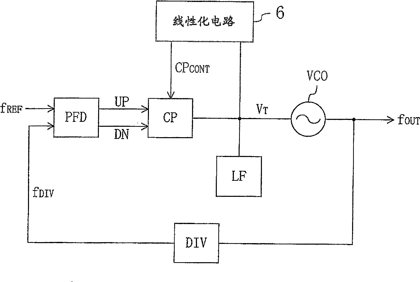
[0048] figure 1 It is a diagram showing the configuration of the PLL frequency synthesizer according to the first embodiment of the present invention.
[0049] In the figure, the PLL frequency synthesizer has a voltage-controlled oscillator VCO, a programmable frequency divider DIV, a phase comparator PFD, a charge pump circuit CP, and a loop filter LF.
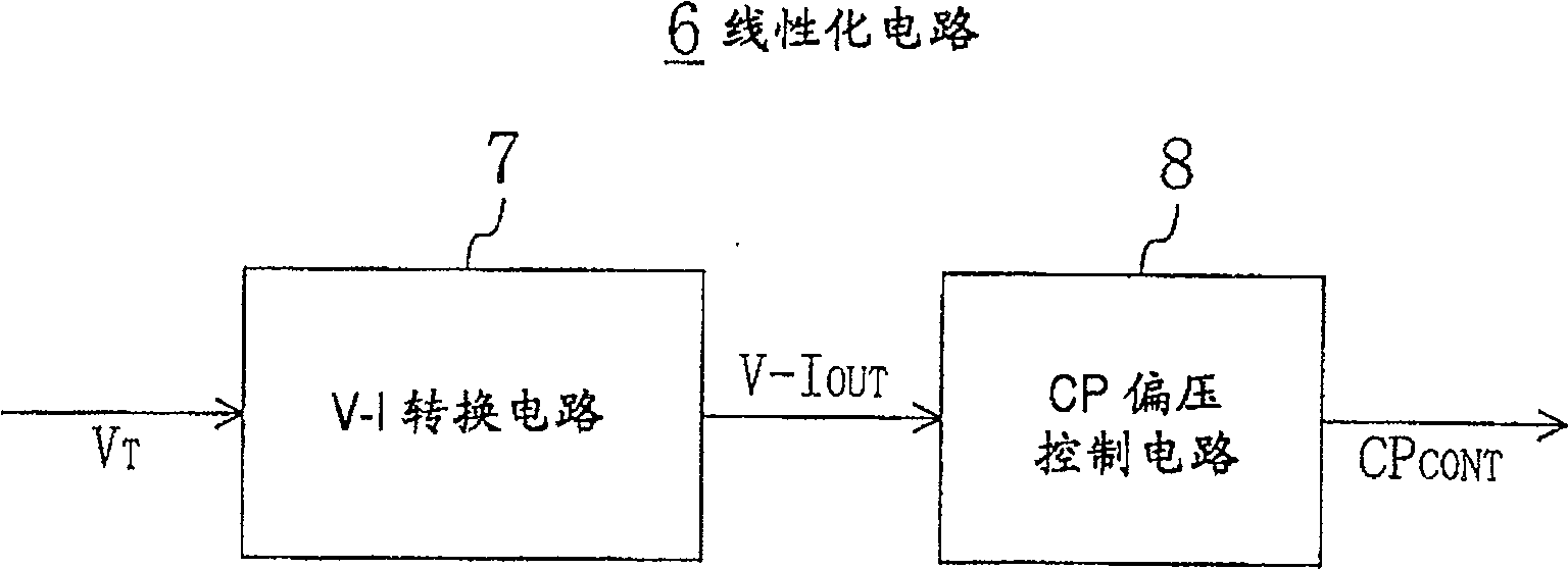
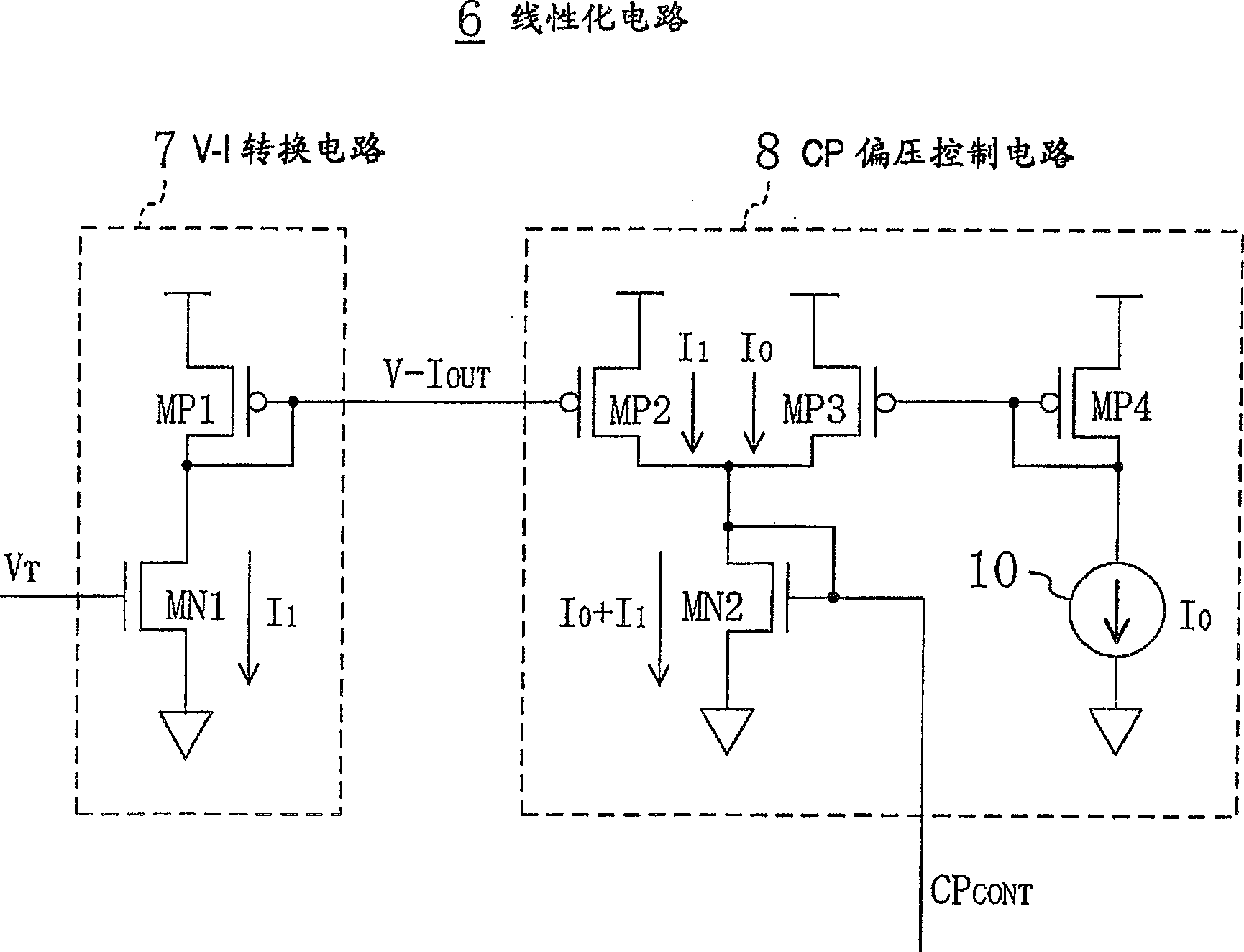
[0050] The voltage-controlled oscillator VCO mentioned above controls the signal V according to the oscillation frequency T The voltage changes the oscillation frequency. The above frequency divider DIV compares the oscillation frequency f from the voltage controlled oscillator VCO with the frequency division ratio corresponding to the channel selection signal input from the outside. OUT Carry out frequency division. The above-mentioned phase comparator PFD detects the output signal f from the above-mentioned division frequency DIV DIV with an externally input reference signal f REF The phase difference between them out...
no. 2 Embodiment approach
[0058] Next, a second embodiment of the present invention will be described. This embodiment is a modification of the linearization circuit 6 shown in the above-mentioned first embodiment.
[0059] which is, Figure 5 In the shown linearization circuit 6', two series circuits of P-type and N-type transistors MP1A and MN1A and other series circuits of P-type and N-type transistors MP1B and MN1B are arranged in the V-I conversion circuit 7'. circuit, the oscillating frequency signal V from the loop filter LF above T They are respectively input to the gates of the two N-type transistors MN1A and MN1B mentioned above. Therefore, with image 3 The shown V-I conversion circuit 7 similarly flows through the current I of the two N-type transistors MN1A and MN1B of each series circuit respectively. 1A , I 1B , according to the oscillation frequency signal V received by the gate of the respective transistor T potential changes. Moreover, in the CP bias control circuit 8', there a...
no. 3 Embodiment approach
[0063] Next, a third embodiment of the present invention will be described. This embodiment is a modification of the linearization circuit 6 shown in the above-mentioned first embodiment.
[0064] which is, Figure 7 The shown linearization circuit 6", in the V-I conversion circuit 7", receives the oscillation frequency control signal V at the gate T An N-type transistor MN3 is disposed between the source of the N-type transistor MN1 and the ground. An operational amplifier 12 is connected to the gate of the N-type transistor MN3 , and the source voltage of the N-type transistor MN1 and a bias voltage generated by the bias voltage generating circuit 11 are input to the operational amplifier 12 . The operational amplifier 12 controls the N-type transistor MN3 such that the source voltage of the N-type transistor MN1 matches the bias voltage generated by the bias voltage generating circuit 11 . in addition, Figure 7 shown in the CP bias control circuit 8, with figure 1 Th...
PUM
 Abstract
Description
Claims
Application Information
 - R&D
- Intellectual Property
- Life Sciences
- Materials
- Tech Scout
- Unparalleled Data Quality
- Higher Quality Content
- 60% Fewer Hallucinations
Browse by: Latest US Patents, China's latest patents, Technical Efficacy Thesaurus, Application Domain, Technology Topic, Popular Technical Reports.
© 2025 PatSnap. All rights reserved.Legal|Privacy policy|Modern Slavery Act Transparency Statement|Sitemap|About US| Contact US: help@patsnap.com


