Seasoner sponging drying machine group

A drying unit and seasoning technology, applied in dryers, drying solid materials, heating to dry solid materials, etc., can solve the problems of increasing pollution, reducing heat energy effect, complex process structure, etc., to improve drying efficiency and prevent sticking. The effect of wall phenomenon and yield improvement

Inactive Publication Date: 2009-08-05
JIANGSU XIANFENG DRYING ENG
View PDF10 Cites 3 Cited by
  • Summary
  • Abstract
  • Description
  • Claims
  • Application Information

AI Technical Summary

Problems solved by technology

Both the cone and cylinder of the drying tower are equipped with air brush tubes, and then the air intake pipe is used to blow off the powder sticking to the tower wall through the air brush. Cooling, which brings about an increase in energy consumption, thereby reducing the thermal effect
[0004] Both the drying tower and the cyclone separator of the centrifugal spray drying unit have finished product output. Since the finished product output is scattered, it is difficult to ensure that the environment of each outlet meets the hygienic requirements.
In addition, the temperature of the finished product is high when it leaves the unit, and it needs to be cooled before packaging, which increases the possibility of pollution

Method used


Image

  • Seasoner sponging drying machine group
  • Seasoner sponging drying machine group
  • Seasoner sponging drying machine group

Examples


Embodiment Construction

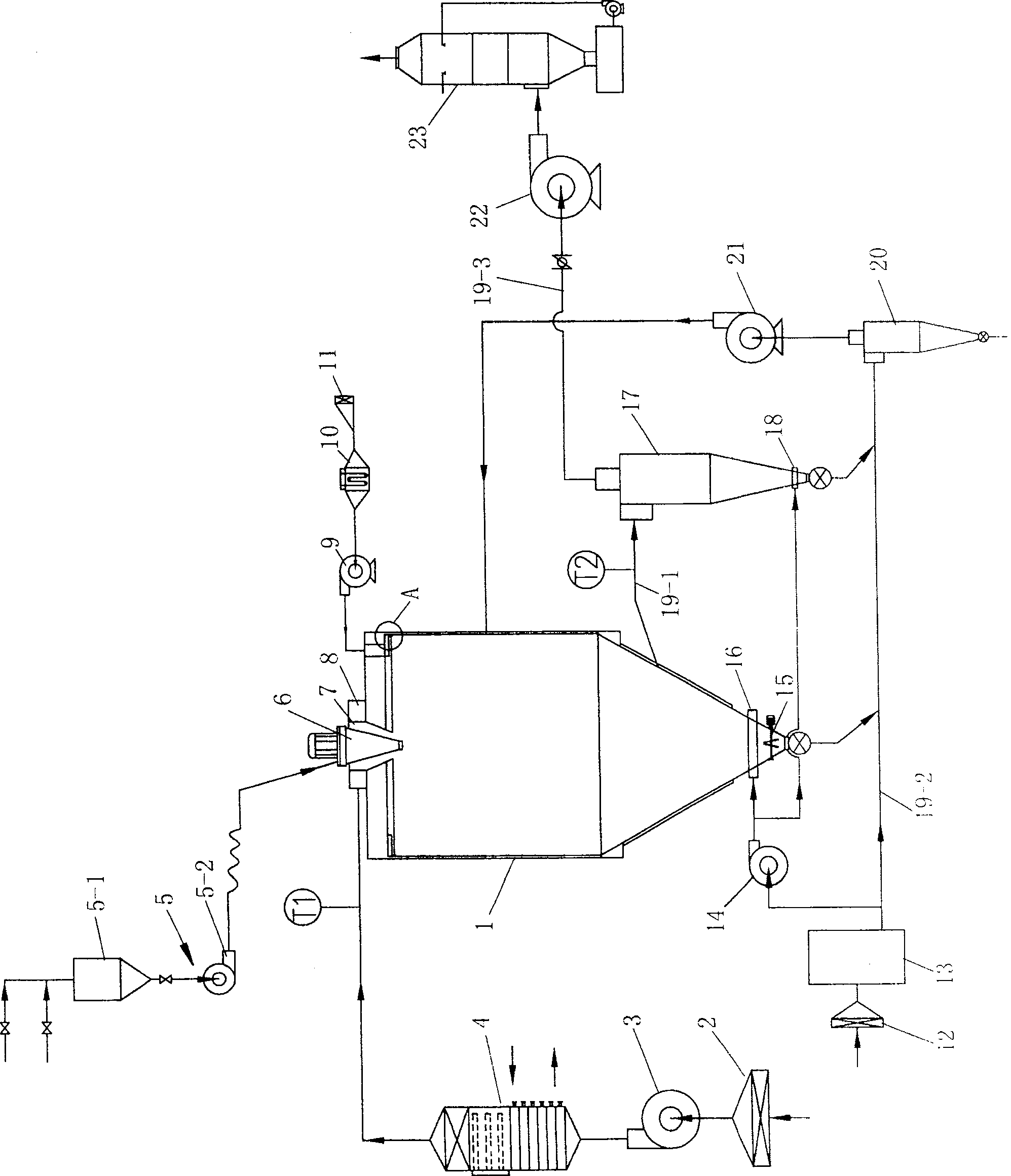
[0032] See figure 1 , the present invention includes feeding device 5, drying tower 1, No. 1 fan 3, No. 1 heater 4, primary cyclone separator 17 and water film deduster 23. The feeding device 5 includes a hopper 5-1 and a feeding pump 5-2, and the feeding pump is a peristaltic pump.

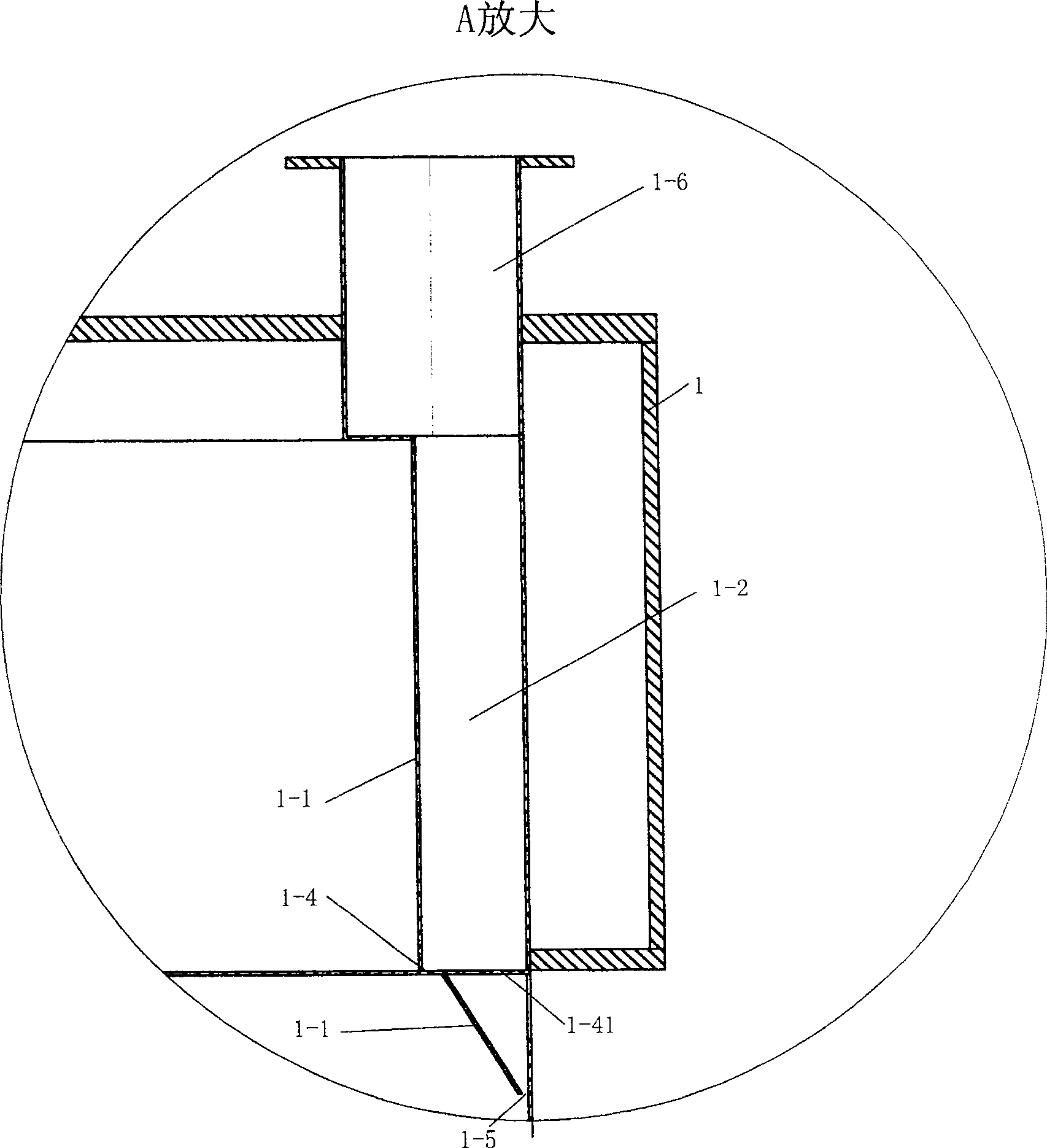
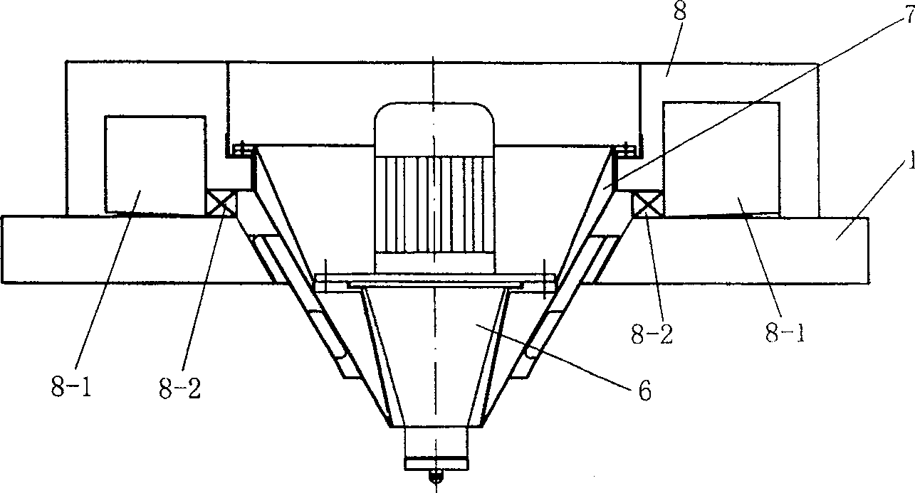
[0033] See figure 1 , 3 and 4, the central hot air inlet at the top of the drying tower 1 is provided with a hot air distributor 7 and an atomizer 6 installed in the center of the hot air distributor and connected to the feeding device 5 . The top of the drying tower 1 is provided with an air channel plate 8 with a volute-shaped air channel 8-1, the inlet of the air channel plate 8 is connected to the output pipeline of No. 1 heater 4, and the outlet of the air channel plate 8 is connected to the hot air distributor. 7 import connections. The volute-shaped air channel 8-1 of the air channel plate 8 has a square cross-section, its cross-section gradually shrinks and the bottom surface is incli...


PUM


Abstract

The invention includes a feeding device, a drying tower, a No. 1 fan, a No. 1 heater, a first-stage cyclone separator and a water film dust collector; a hot blast distributor is installed at the central hot blast inlet of the drying tower top and installed in the center of the hot blast distributor. And the atomizer connected with the feeding device, the top of the drying tower is provided with an air channel plate with a volute-shaped air channel, the inlet of the air channel plate is connected to the output pipeline of No. 1 heater, and the outlet of the air channel plate is connected to the The inlet connection of the hot air distributor; there is a jacket near the top of the drying tower body, the space between the jacket and the inner wall of the tower body is the air inlet channel for sweeping the wall, and the ring between the bottom of the jacket and the inner wall of the tower body The gap is the air outlet, and the wind passes through the annular gap to form a wall-sweeping wind. The invention adopts the air duct spiral cutting and wall-sweeping air inlet technology, which not only improves the drying efficiency, but also forms a wind film on the drying tower wall by providing the wall-sweeping wind. , The air film isolates the powder from contacting the tower wall to prevent the phenomenon of sticking to the wall.

Description

technical field [0001] The invention relates to a spray drying equipment. Background technique [0002] Spray drying technology has been widely used in the chemical, pharmaceutical and food industries in the 1990s to dry emulsions, suspensions and viscous liquid materials. At the same time, according to the nature of the material, spray drying can be carried out in the form of pressure spray or centrifugal spray, so as to obtain spherical or fine particle solid products. A general centrifugal spray drying unit includes a drying tower and at least one cyclone separator. Hot air enters the drying tower, and the feed liquid passes through the centrifugal atomizer to form extremely fine mist droplets, which complete heat and mass transfer with the hot air in the drying tower. process, drying into finished products, and the dried products are continuously output from the receiving port at the bottom of the drying tower. The hot and humid gas containing fine particles enters the ...

Claims


Application Information

Patent Timeline
Patent Type & Authority Patents(China)
IPC IPC(8): F26B3/12F26B17/10
Inventor 周友来查协芳顾建新陈进元
Owner JIANGSU XIANFENG DRYING ENG
Why Eureka
Try Eureka