Supercharge Your Innovation With Domain-Expert AI Agents!

Operational amplifier and operating method thereof

An operational amplifier and coupling technology, which is applied in the direction of analog-to-digital converters, differential amplifiers, DC-coupled DC amplifiers, etc., can solve the problem of increasing chip power load and achieve the effect of reducing flicker noise

Active Publication Date: 2009-12-02
MEDIATEK INC
View PDF5 Cites 0 Cited by
  • Summary
  • Abstract
  • Description
  • Claims
  • Application Information

AI Technical Summary

Problems solved by technology

In addition, parasitic capacitance will also increase the power load of the chip

Method used


Image

  • Operational amplifier and operating method thereof
  • Operational amplifier and operating method thereof
  • Operational amplifier and operating method thereof

Examples


Embodiment

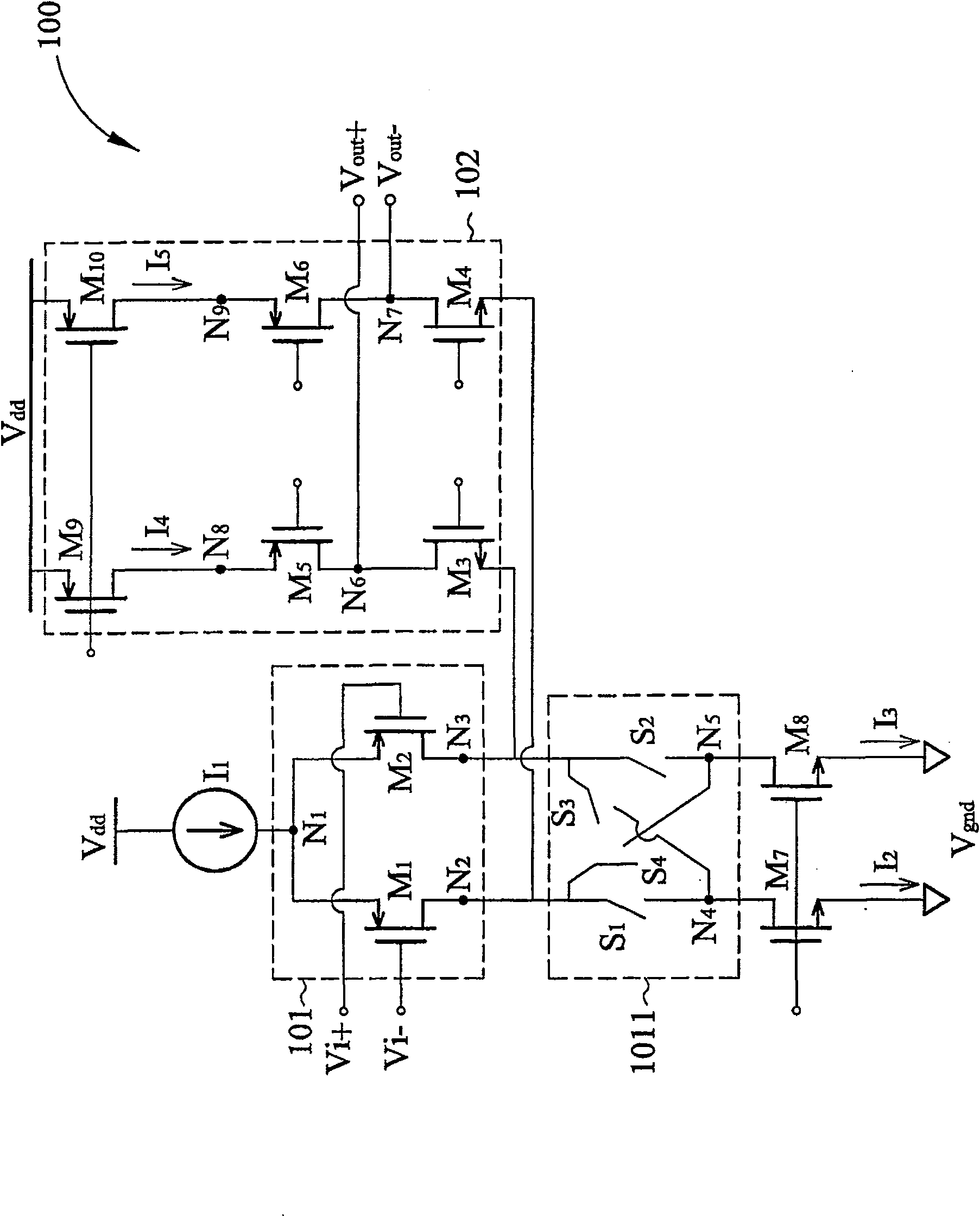
[0041] Please refer to figure 1 . figure 1 is a circuit diagram showing an operational amplifier 100 according to the first embodiment of the present invention. The operational amplifier 100 includes an input stage 101 and a load stage 102 . The input stage 101 includes a first transistor M 1 with the second transistor M 2 . first transistor M 1 with the second transistor M 2 form a differential pair and at terminal N 1 coupled together, while the first current source I 1 more coupled to terminal N 1 . first transistor M 1 The gate of the second transistor M 2 The gate is used to receive the corresponding to the first frequency band f in- A pair of differential input signals Vi+ and Vi-. In addition, the modulation device 1011 is coupled to the first transistor M 1 The drain terminal N 2 and the second transistor M 2 The drain terminal N 3 , the first connection point N 4 coupled to the second current source I 2 (e.g. N-type transistor M 7 ), the second con...


PUM


Abstract

An operational amplifier is disclosed. The operational amplifier comprises an input stage and a loading stage. The input stage receives a differential input signal pair corresponding to a first frequency band. The loading stage is coupled to the input stage. The loading stage outputs an amplified differential output at output nodes. The loading stage comprises a flicker noise source and a modulating device. The modulating device is coupled to the flicker noise source. The modulating device modulates flicker noises into a second frequency band. The modulating device is not within a signal path.

Description

technical field [0001] The present invention relates to an operational amplifier, in particular to a folded cascode operational amplifier and its operating method. Background technique [0002] In the application of analog to digital converter (analog to digital converter, ADC) chip, the processing of noise signal is the primary consideration. For example, in an ADC or a digital to analog converter (DAC), increasing the signal-to-noise ratio (SNR) is considered an important design consideration. An important factor affecting SNR is the flicker noise of the transistor. Flicker noise is an unwanted energy level generated when many dangling bonds appear at the interface between the oxide layer at the gate terminal of a transistor and the silicon substrate. As charge carriers move to the interface, some carriers are randomly attracted and then released to the energy level allowing the drain current to generate flicker noise. Therefore, reducing flicker noise is a major design...

Claims


Application Information

Patent Timeline
Patent Type & Authority Patents(China)
IPC IPC(8): H03F3/45H03F1/26H03M1/12
Inventor 黄胜瑞
Owner MEDIATEK INC
Features
  • R&D
  • Intellectual Property
  • Life Sciences
  • Materials
  • Tech Scout
  • Unparalleled Data Quality
  • Higher Quality Content
  • 60% Fewer Hallucinations
Learn More