Gallium nitride-based compound semiconductor lihgt-emitting device
A light-emitting device, gallium nitride-based technology, applied in the direction of semiconductor devices, electrical components, circuits, etc., can solve problems such as inability to improve light emission output, internal quantum efficiency reduction, etc., to achieve large light emission output, good crystallinity, Effect of Excellent Light Extraction Efficiency
- Summary
- Abstract
- Description
- Claims
- Application Information
AI Technical Summary
Problems solved by technology
Method used
Image
Examples
example 1
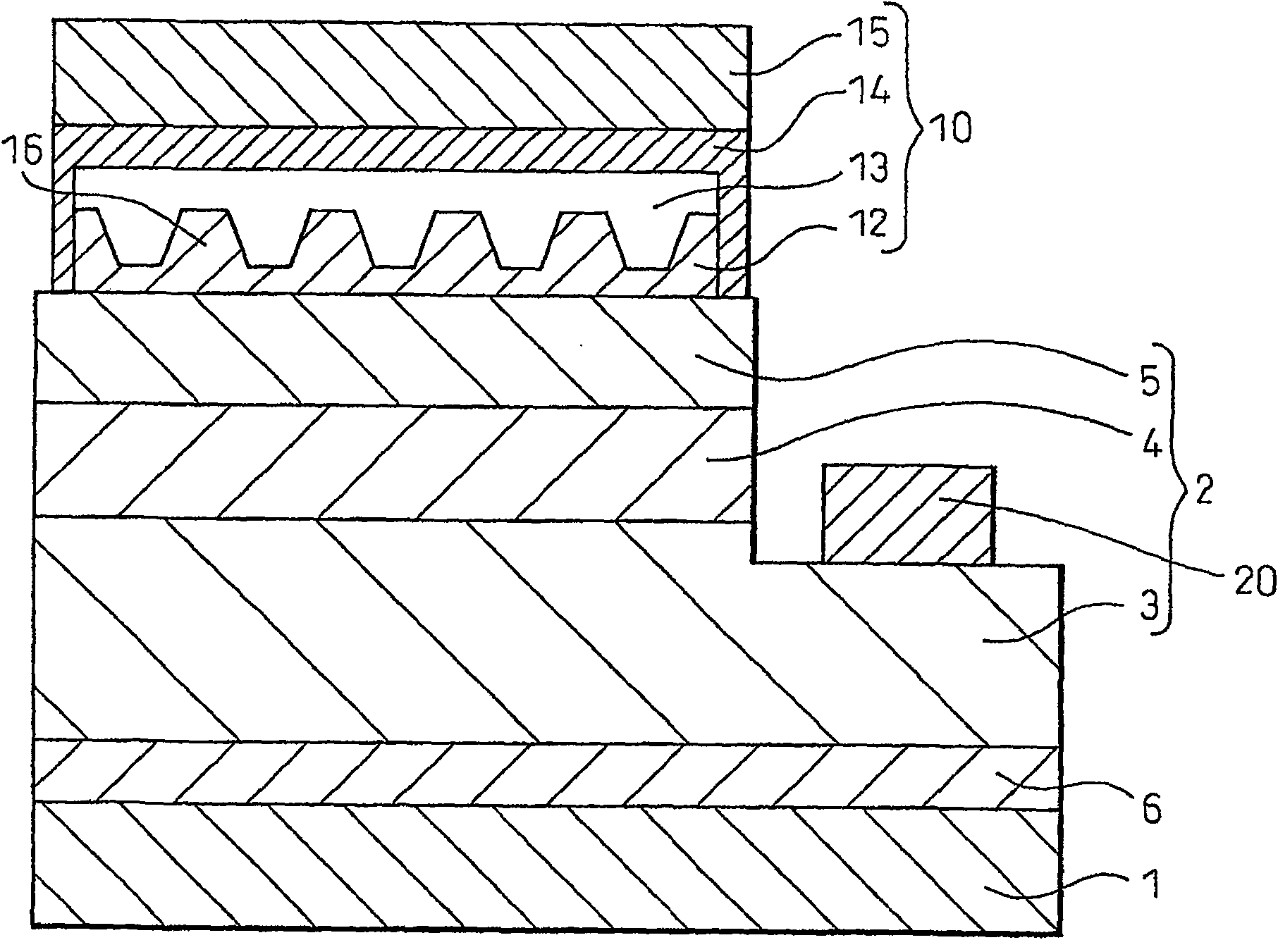
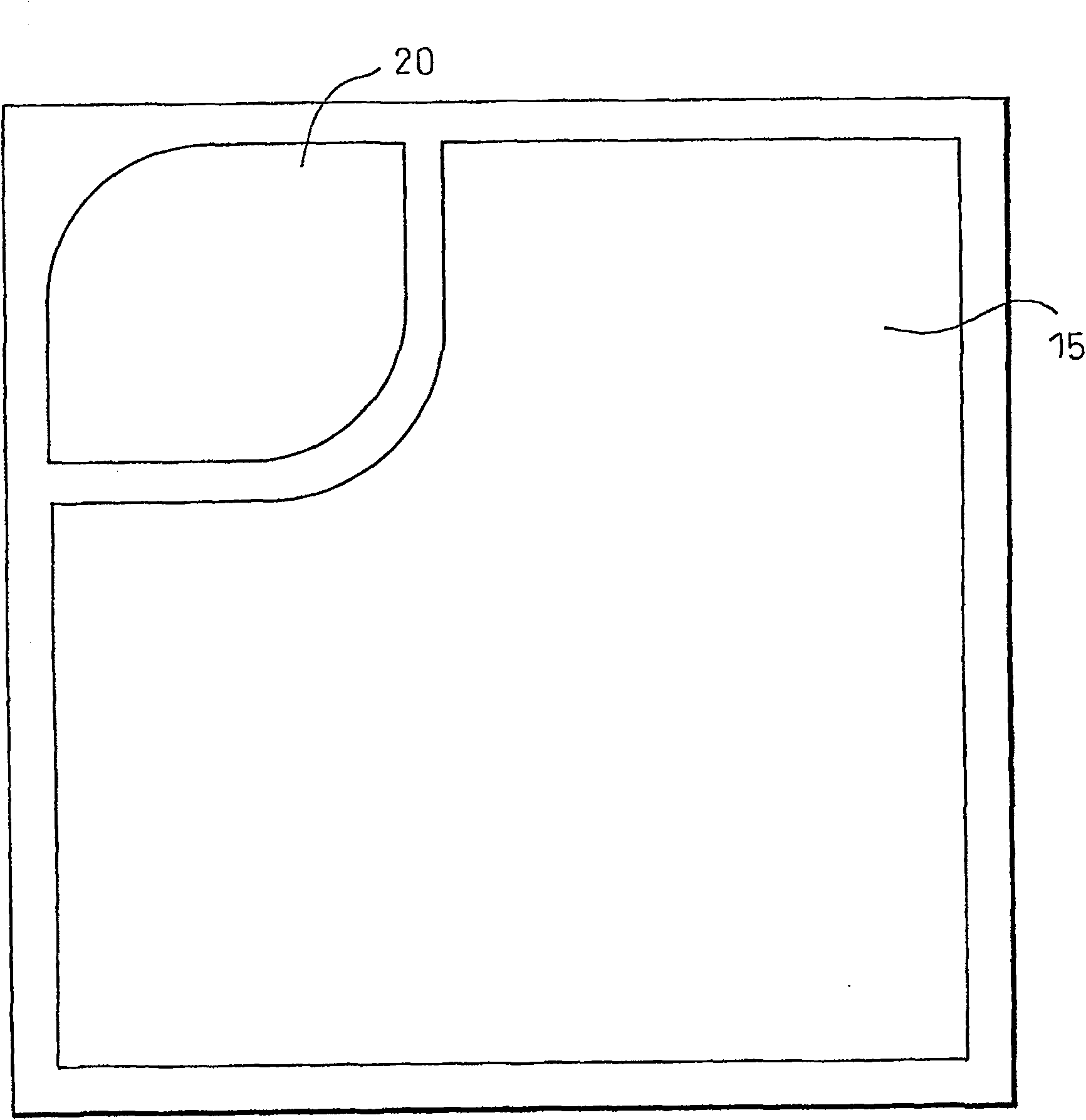
[0106] figure 1 is a schematic diagram showing a cross-section of a gallium nitride-based compound semiconductor light-emitting device fabricated in this example, and figure 2 is a schematic diagram showing a plan view thereof. A gallium nitride-based compound semiconductor layer (2) is formed on a sapphire substrate (1) with an AlN buffer layer (6) interposed therebetween. The gallium nitride-based compound semiconductor layer (2) includes: an 8 μm thick undoped GaN base layer (base layer), a 2 μm thick Ge-doped n-type GaN contact layer, and a 0.02 μm thick Si-doped GaN contact layer. Miscellaneous n-type In 0.1 Ga 0.9 An n-type semiconductor layer (3) formed by an N-clad layer; five layers of 16 nm-thick Si-doped GaN barrier layers and five layers of 2.5 nm-thick In 0.06 Ga 0.94 The light-emitting layer (4) of the multi-quantum well structure constructed by N well layer and finally forming a barrier layer on top of the uppermost well layer; and by sequentially forming ...
example 2
[0125] Figure 11 is a schematic diagram showing a cross-section of a gallium nitride-based compound semiconductor light-emitting device manufactured in this example, and its plan view is the same as that in Example 1. figure 2 same as shown in the schematic. As in Example 1, a gallium nitride-based compound semiconductor layer (2) was formed on a sapphire substrate (1) with an AlN buffer layer (6) interposed therebetween.
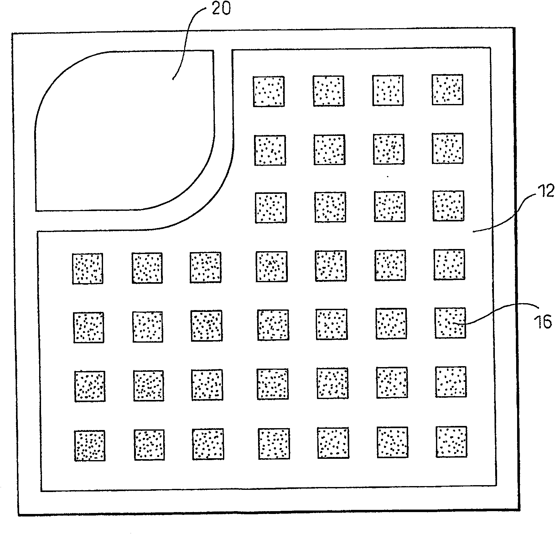
[0126] The structure of the positive electrode in this example is as follows. By forming the positive electrode contact layer (11) formed by 20nm thick ITO, by 180nm thick SiO 2 Formed transparent material layer (12), reflective metal layer (13) formed by 100nm thick Ag, covering layer (14) formed by 500nm thick Rh, and Au, Ti, Al, Ti and Au (thickness respectively The junction layer (15) of five-layer structure is 50nm, 20nm, 10nm, 100nm and 200nm), and the positive electrode (10) is formed on the p-type AlGaN contact layer. As in Example 1, in SiO ...
PUM
 Abstract
Description
Claims
Application Information
 - R&D
- Intellectual Property
- Life Sciences
- Materials
- Tech Scout
- Unparalleled Data Quality
- Higher Quality Content
- 60% Fewer Hallucinations
Browse by: Latest US Patents, China's latest patents, Technical Efficacy Thesaurus, Application Domain, Technology Topic, Popular Technical Reports.
© 2025 PatSnap. All rights reserved.Legal|Privacy policy|Modern Slavery Act Transparency Statement|Sitemap|About US| Contact US: help@patsnap.com


