Flat plate type heat conduction heat flux sensor based on direct temperature measurement

A technology of heat flow sensor and temperature sensor, which is applied in calorimeters, heat measurement, and thermometers using electric/magnetic elements that are directly sensitive to heat, can solve problems such as low precision, high cost, and complicated manufacturing process, and achieve high The effect of high-precision temperature measurement, easy manufacturing process, and small heat flow measurement

Inactive Publication Date: 2010-01-13
BEIHANG UNIV
View PDF2 Cites 0 Cited by
  • Summary
  • Abstract
  • Description
  • Claims
  • Application Information

AI Technical Summary

Problems solved by technology

At present, most heat conduction and heat flow sensors work based on the principle of temperature difference measurement. According to the thermoelectric effect, the temperature difference signal is converted into an electrical signal and directly used as the input of the sensor signal processing circuit. This kind of sensor has high sensitivity, but it can only reflect the temperature difference signal. The process is complex and expensive
The other is based on the principle of temperature measurement. This sensor can not only provide temperature difference signal but also provide temperature information. However, this sensor has high requirements for temperature measurement accuracy, and the early A / D conversion technology is difficult to meet the accuracy requirements of heat flow calculation.
[0009] Most of the structures of existing heat flow sensors are designed based on the principle of temperature difference measurement (thermoelectric effect), the manufacturing process is complicated, and the measurement signal is single. Low, cannot be used in small heat flow measurement

Method used


Image

  • Flat plate type heat conduction heat flux sensor based on direct temperature measurement
  • Flat plate type heat conduction heat flux sensor based on direct temperature measurement
  • Flat plate type heat conduction heat flux sensor based on direct temperature measurement

Examples


Embodiment Construction

[0025] The present invention will be further described in detail below in conjunction with the accompanying drawings.

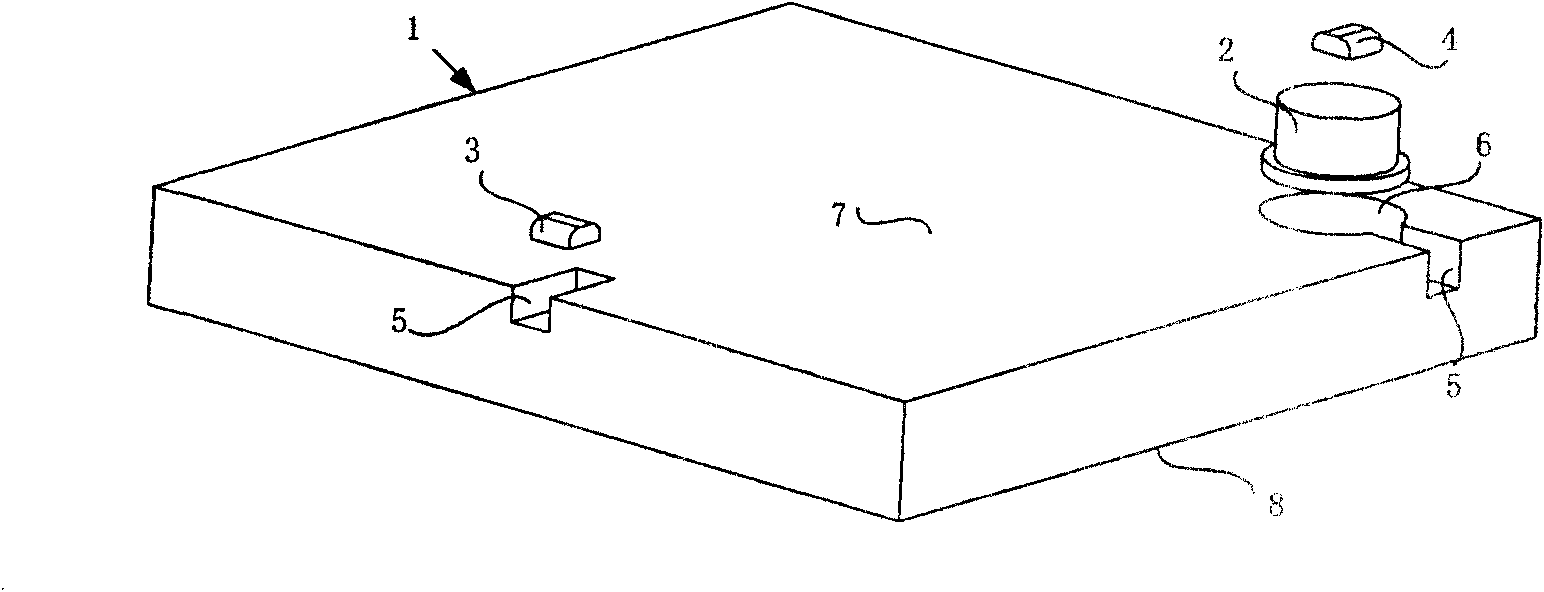
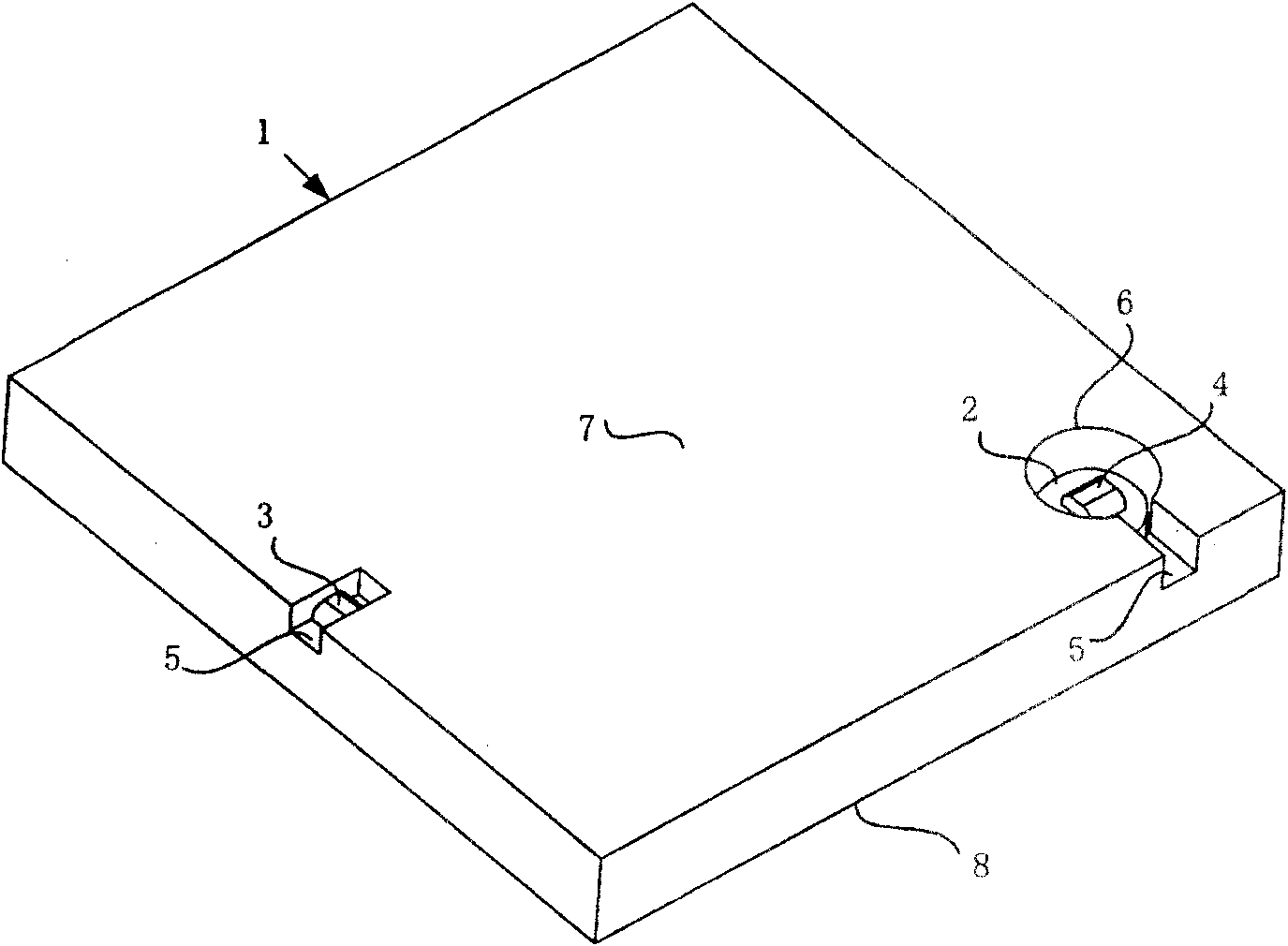
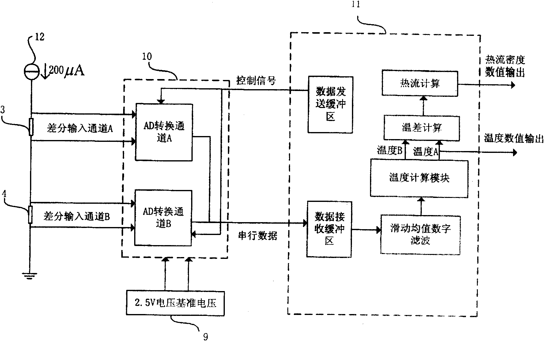
[0026] The present invention is a flat plate heat conduction heat flow sensor based on direct temperature measurement, such as figure 1 , figure 2 , image 3 As shown, it includes a temperature measurement unit and a measurement circuit. The temperature measurement unit includes: a flat plate 1, an embedded boss 2, two identical temperature sensors A3 and a temperature sensor B4. The upper surface 7 of the flat plate 1 is provided with two grooves 5, the grooves 5 are respectively located on two different sides of the upper surface 7, the depth of the grooves 5 is less than the thickness of the flat plate 1, and one of the grooves 5 is connected with a through hole 6 . The embedding boss 2 is tightly embedded in the through hole 6 after being coated with heat-conducting silicone grease, and the bottom of the embedding boss 2 is in the same plane as the lo...


PUM


Abstract

The invention discloses a planar heat conducting heat flow transducer based on direct temperature measurement. The planar heat conducting heat flow transducer comprises a temperature measurement unit and a measurement circuit, wherein the temperature measurement unit comprises a panel, an embedded lug boss, a temperature transducer A and a temperature transducer B which are the same; the upper surface of the panel is provided with two grooves, and one of the grooves is connected with a through hole; the embedded lug boss is embedded in the through hole closely; the temperature transducer B is fixed above the embedded lug boss; the temperature transducer B is fixed in the other groove which is not connected with the through hole; and the measurement circuit comprises an A / D converter, an MCU and a constant flow source. The temperature measurement unit has a simple structure, only requires two temperature transducers, a red bronze panel, and a nylon embedded lug boss, and has easily realized manufacturing process. With a 24 bit AD conversion chip, high accuracy temperature measurement is realized; and small heat flow measurement can be realized through two paths of temperature measurement by adopting a principle of the temperature measurement type heat flow transducer.

Description

technical field [0001] The invention relates to the technical field of heat flow detection in a heat control system, in particular to a flat plate heat conduction heat flow sensor based on direct temperature measurement. Background technique [0002] Heat flux is an important parameter to characterize heat transfer and exchange. In the case of contact heat conduction, the heat flux can be expressed by the following formula according to Fourier's law of heat conduction: [0003] q=-λ(dt / dx) (1) [0004] Among them, q is the heat flux density, λ is the thermal conductivity of the material, (dt / dx) is the temperature gradient of the object along the x direction, that is, the temperature change rate of the object in the x direction. [0005] When there are two isothermal surfaces T and T+ΔT, the heat flux can be expressed as: [0006] q=-λ(ΔT / Δx) (2) [0007] Where ΔT is the temperature difference between the two isothermal surfaces, Δx is the distance between the two isother...

Claims


Application Information

Patent Timeline
Patent Type & Authority Patents(China)
IPC IPC(8): G01K17/00G01K7/18
Inventor 李运泽刘东晓刘佳王玉莹李运华王浚
Owner BEIHANG UNIV
Why Eureka
Try Eureka