
Hydration polisher

A polishing machine and hydration technology, which is applied in the field of polishing machines, can solve problems such as processing quality, processing accuracy, and processing efficiency, and achieve the effects of low cost of machine equipment, uniform supply, and simple processing conditions

Inactive Publication Date: 2010-03-10
ZHEJIANG UNIV OF TECH
View PDF6 Cites 0 Cited by
  • Summary
  • Abstract
  • Description
  • Claims
  • Application Information

AI Technical Summary

Problems solved by technology

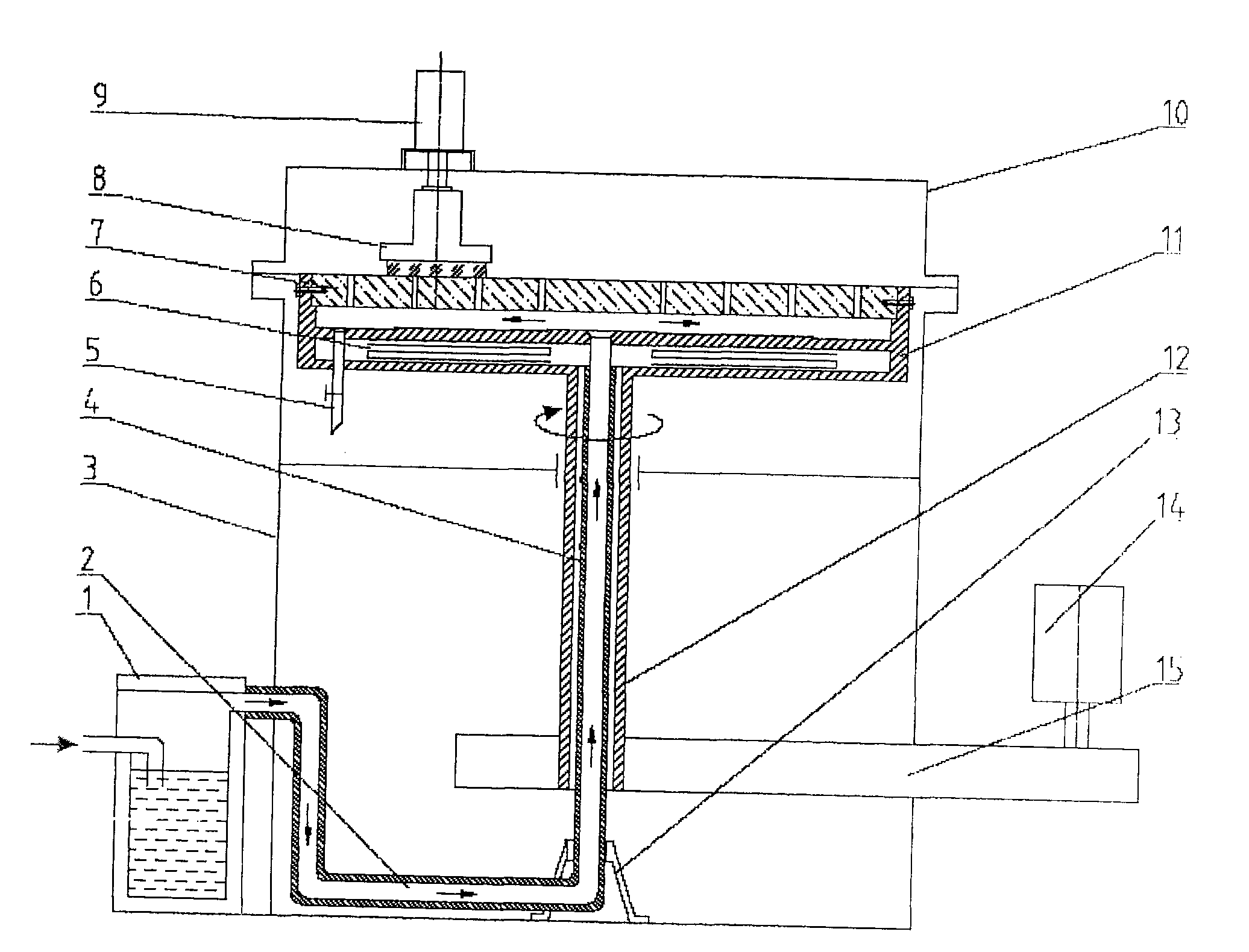
[0011] In order to overcome the shortcomings of existing various polishing machines that cannot take into account processing quality, processing accuracy and processing efficiency when processing sapphire crystals, the present invention provides a polishing machine that has both good processing quality and high processing accuracy when processing sapphire crystals. High-efficiency hydration polishing machine

Method used


Image

  • Hydration polisher

Examples


Embodiment Construction

[0024] The present invention will be further described below in conjunction with the accompanying drawings.

[0025] refer to figure 1 , a hydration polishing machine, comprising a machine base 3, a main shaft motor 14, a main shaft 12, a polishing disc 7, a vacuum suction cup 8 and a suction cup motor 9, the main shaft motor 14 is in transmission connection with the main shaft 12, and the main shaft 12 is installed on the machine base 3, the upper end of the main shaft 12 is transmission connected with the polishing disc 7, the vacuum suction cup 8 is located above the polishing disc 7, the vacuum suction cup 8 is transmission connected with the suction cup motor 9, and the hydration polishing machine also includes steam Generator 1, steam pipe 2 and base plate 11, the outlet of the steam generator 1 is connected to the steam pipe 2, the inside of the main shaft 12 is provided with a through hole, and the steam pipe 2 runs through from bottom to top The through hole, the upp...


PUM


Abstract

The invention provides a hydration polishing machine, comprising a frame, a main shaft motor, a main shaft, a polishing disk, a vacuum chuck and a sucker motor. The main shaft motor is connected withthe main shaft in a transmission way. The main shaft is arranged inside the frame. The upper end of the main shaft is connected with the polishing disk in a transmission way. The vacuum chuck is located on the upper part of the polishing disk. The vacuum chuck is connected with the sucker motor in a transmission way. The hydration polishing machine also comprises a steam generator, a steam delivery pipe and a basal disk. The outlet of the steam generator is connected with the steam delivery pipe. The inside of the main shaft is provided with a through hole. The steam delivery pipe runs throughthe through holes from bottom to top. The upper end of the main shaft is fixedly connected with the center of the basal disk. The upper part of the basal disk is fixedly connected with the polishingdisk. A transition hollow cavity is arranged between the basal disk and the polishing disk. The steam delivery pipe passes through the basal disk and is communicated with the transition hollow cavity.The bottom of the transition hollow cavity is provided with a drain pipe. The polishing disk is provided with a through hole. When the hydration polishing machine is used for processing the sapphirecrystal, the process quality is excellent, the process precision and the process efficiency are high.

Description

technical field [0001] The invention relates to the field of polishing machines, in particular to a polishing machine for high-brightness LED sapphire crystal polishing. Background technique [0002] Polishing is an important method to obtain a high-quality sapphire crystal surface. The semiconductor material system for manufacturing high-brightness LEDs has stricter requirements than traditional LEDs. In the heterostructure, the small internal stress of the sapphire wafer due to grinding, polishing, etc. will change the lattice constant of the AlN, AlGaN, and GaN films, resulting in the generation of film stress. When the film accumulates too much stress, its surface Many small bumps, cracks and voids will be produced; in addition, scratches on the substrate surface can also be reflected on the surface of the epitaxial layer, and good surface roughness is a necessary condition for the growth of low dislocation 106-1010cm-3GaN films; sapphire wafers The surface lattice inte...

Claims


Application Information

Patent Timeline
Patent Type & Authority Patents(China)
IPC IPC(8): B24B9/16B24B57/02
Inventor 文东辉邓乾发陶黎洪滔
Owner ZHEJIANG UNIV OF TECH
Learn More