Multifunction nitration back nitration integrated auto dynamic film bioreactor

A technology of nitrification and denitrification and bioreactor, which is applied in the field of multifunctional nitrification and denitrification integrated self-generated dynamic membrane bioreactor, which can solve the problems of membrane pollution and expensive cost of membrane units, so as to improve the treatment level and biodegradability Effect

Inactive Publication Date: 2007-07-18
TONGJI UNIV
View PDF0 Cites 19 Cited by
  • Summary
  • Abstract
  • Description
  • Claims
  • Application Information

AI Technical Summary

Problems solved by technology

[0005] The purpose of the present invention is to provide a multifunctional nitrification and denitrification integrated self-generating system that occupies less land, is economical and convenient, can remove organic matter and ammonia nitrogen that are difficult to degrade, and can overcome the problems of expensive membrane unit cost and membrane pollution in membrane bioreactors. Dynamic Membrane Bioreactor

Method used


Image

  • Multifunction nitration back nitration integrated auto dynamic film bioreactor

Examples


Embodiment 1

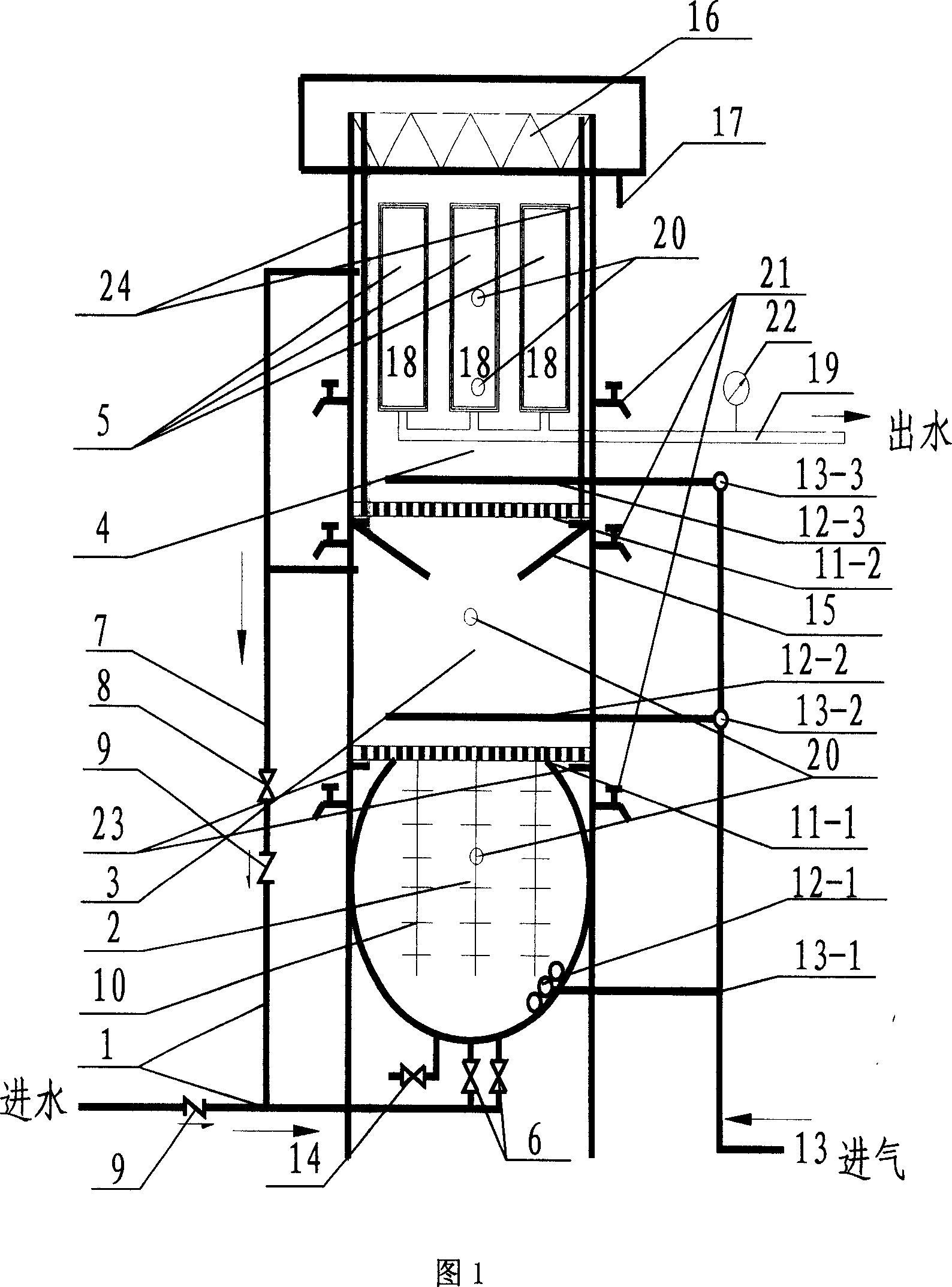
[0043] The multifunctional nitrification and denitrification integrated self-generated dynamic membrane bioreactor has a cylindrical structure, which is composed of a water inlet system 1, a pretreatment reaction area 2, an aeration reaction area 3, and a semi-aeration area 4 from bottom to top. As shown in Figure 1, the pretreatment reaction zone 2, the aeration reaction zone 3 and the semi-aeration zone 4 are all separated by perforated plates, which facilitate the passage of water, and at the same time support and define each functional zone. in:

[0044] The water inlet system 1 is composed of a water inlet 6 and a jet gravity return pipe 7. Both the water inlet pipe and the return pipe 7 are provided with a one-way valve 9 to avoid backflow of water in case of an accident. The use of the return pipe 7 depends on the reaction state of the pretreatment reaction zone. If the pretreatment reaction zone is anoxic reaction, it is used, and if the pretreatment reaction zone is a...

Embodiment 2

[0053] The reactor obtained in Example 1 was used to treat domestic sewage in a certain community.

[0054] The domestic sewage enters the multifunctional nitrification and denitrification integrated self-generated dynamic membrane bioreactor, and the airflow inside the reactor pushes the suspended packing into a flowing state, and the domestic sewage is decomposed under the action of the biofilm of the suspended packing in the pretreatment area. The hydraulic retention time in the pretreatment area is 1~2h, and the dissolved oxygen is 1~2mg / L; after entering the aeration reaction area, under the action of micro aeration, the sewage is further purified by activated sludge, and part of the denitrification is completed. The hydraulic retention time in the aerated reaction zone is 0.5h, and the dissolved oxygen is below 0.5mg / L; after that, it enters the semi-aerated reaction zone (the zone is anoxic at this time) for further denitrification, and the hydraulic retention time in th...


PUM

PropertyMeasurementUnit
turbidityaaaaaaaaaa

Abstract

This invention belongs to environment protection technique field, which concretely relates to a multifunction nitrification anti-nitrification integrated self-generation dynamic state membrane bioreactor. This reactor is cartridge structure, which is made up of half aerating reacting region, aerating reacting region, and fore treatment reacting region from top to inferior surface. Fore treatment reacting region loads bulking agent. It can change reaction style (anaerobic or aerobic) with different water quality; self-generation dynamic state membrane components are in half aerating reacting region; recirculation of recirculation equipment is no apposition dynamia recirculation, and depends on filament band dynamia generated by weight and inletting water pump. This invention overcomes known membrane components of membrane bioreactor is of high cost, not easy to clean membrane pollution, high energy expenditure of recirculating pump and aerating. It has advantages of good water quality, multifunction, using little ground, convenient to use. It is suitable for processing industrial sewage and domestic sewage.

Description

technical field [0001] The invention belongs to the technical field of environmental protection, and in particular relates to a multifunctional integrated self-generated dynamic membrane bioreactor for nitrification and denitrification. Background technique [0002] The membrane bioreactor (MBR, membrane bioreactor) formed by the combination of membrane separation and bioreactor is considered to be the most developed in the 21st century due to its reliable effluent quality, convenient operation, compact structure, and small footprint. One of the prospects for sewage treatment. [0003] The biological unit of the membrane bioreactor mostly adopts the activated sludge method, and the membrane treatment unit used mostly uses microfiltration or ultrafiltration membranes made of organic or inorganic materials. Its main feature is to use the characteristics of membrane separation to separate excellent effluent from the activated sludge mixture in the bioreactor, and at the same t...

Claims


Application Information

Patent Timeline
Patent Type & Authority Applications(China)
IPC IPC(8): C02F3/30
Inventor 王荣昌郭冀峰夏四清赵建夫
Owner TONGJI UNIV
Why Eureka
Try Eureka