Method and device for recoverying and using afterheat of furnace quench belt of ceramic production line

A waste heat recovery and production line technology, applied in ceramic material production, furnace, waste heat treatment, etc., can solve the problems of uneven droplet size, uneven powder particle size, and low powder output, etc., which is conducive to popularization and energy consumption. The effect of reducing and saving energy consumption

Inactive Publication Date: 2007-07-18
饶有信
View PDF0 Cites 7 Cited by
  • Summary
  • Abstract
  • Description
  • Claims
  • Application Information

AI Technical Summary

Problems solved by technology

In this kind of drying tower, it is necessary to equip a hot blast stove or burn oil to heat the air at normal temperature, so that the dry mist mud droplets sent into the drying chamber are heated into green powder. If the injection temperature is not high and the size of the droplets is not uniform, it will cause The particle size of the billet powder is uneven, and the output of the billet powder is not high, so the fuel consumption is high and the production cost is high. According to statistics, the energy cost of the drying tower of a ceramic production line exceeds 20,000 yuan per day, and 700,000 yuan per month. At the same time, due to the consumption of energy, it also has a certain impact on the environment.

Method used


Image

  • Method and device for recoverying and using afterheat of furnace quench belt of ceramic production line
  • Method and device for recoverying and using afterheat of furnace quench belt of ceramic production line

Examples


Embodiment Construction

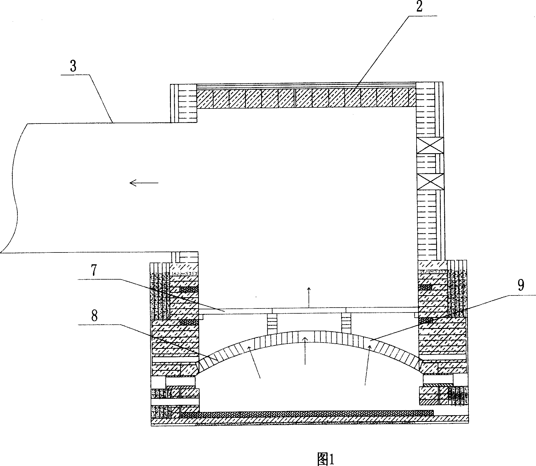
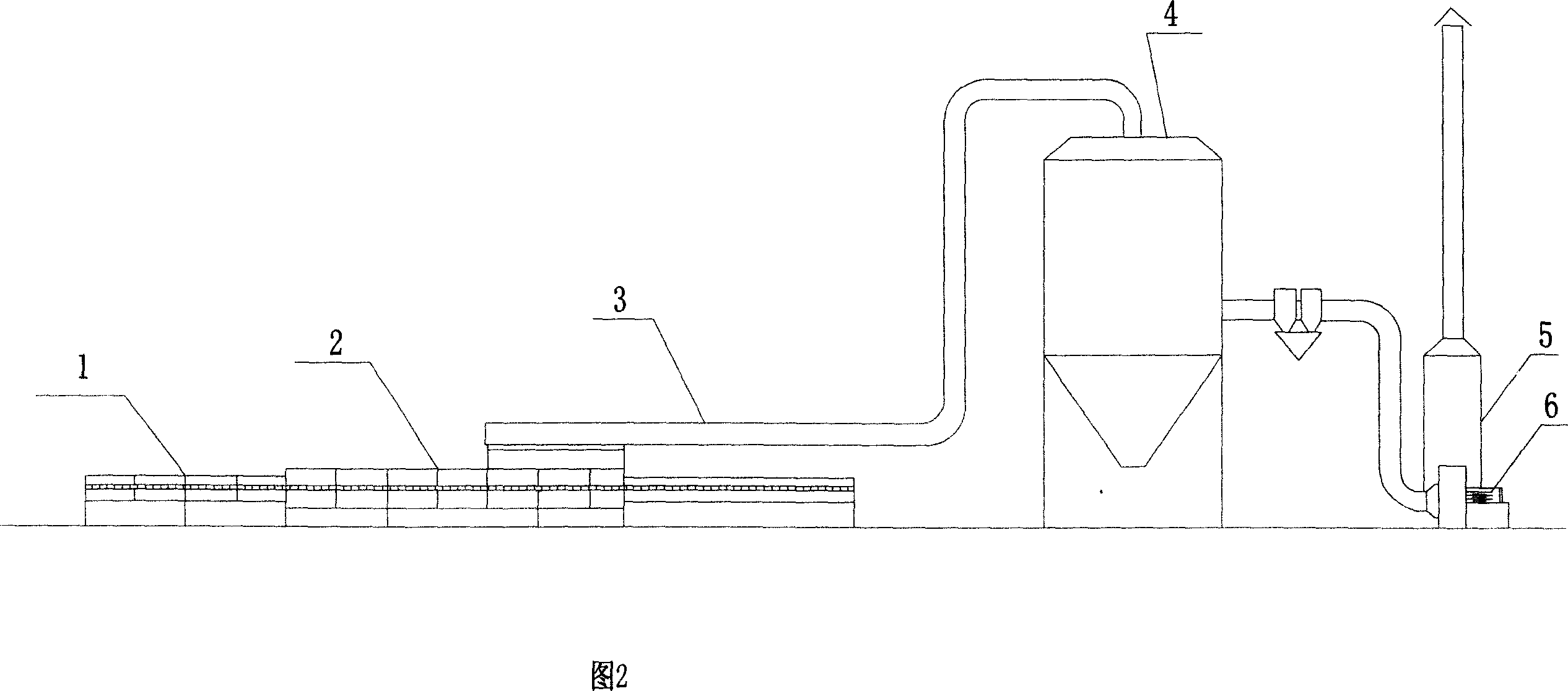
[0017] As shown in Fig. 1 and Fig. 2, the waste heat recovery device of the kiln quenching zone of the ceramic production line of the present invention is to install a hot air pipe 3 on the kiln upper part of the kiln quenching zone 2, and the hot air duct 3 communicates with the furnace chamber , a buffer interlayer is arranged between the upper part of the quenching zone of the kiln and the connected hot air pipe. The upper compartment 7 is plane, the cross section of the lower compartment 8 is arc-shaped, and the two form a vault-shaped structure. The two ends of the upper and lower compartments are fixedly connected with the side wall of the kiln. Silicon carbide plate, the lower compartment 8 is made of mullite or high temperature resistant brick. One end of the hot air pipe 3 communicates with the inner cavity of the upper tower top of the spray drying tower 4, and the other end is connected with the inner cavity of the rear section of the quenching zone 2 of the kiln. ...


PUM


Abstract

The invention discloses kiln furnace quenching belt waste heat recovery method and device in ceramics product line. Its features are that it sets damping area at the top of the kiln furnace inner, then draw out the hot air to utilize. The hot air is send into spray drying tower inner to make it work without another heat source; it sets hot air drawing tube at the upper of the kiln furnace which is connected with furnace chamber. The connecting part is set damping interlayer formed by upper and lower ones set hot gas through hole. The invention has the advantages of low cost, saving energy, environmental protection, etc.

Description

technical field [0001] The invention relates to ceramic manufacturing equipment and a utilization method, in particular to a waste heat recycling method and device for a kiln quenching zone of a ceramic production line. Background technique [0002] In the ceramic firing process of the ceramic manufacturing process, the firing temperature is about 1200 ° C, and then the ceramic is cooled by blowing cold air in the quenching zone of the kiln. Since the temperature change of the ceramic at this stage needs to be controlled within a certain range, If the temperature changes too much, there will be quality problems such as ceramic cracks. Therefore, the kiln roof of the existing kiln quenching zone is a closed structure. Even if the temperature in this section reaches 500-700°C, no one has thought of using it. It’s all wasted, and because the general exhaust fan can withstand a temperature of 250°C at most, it can’t bear this high temperature, and can’t effectively extract its h...

Claims


Application Information

Patent Timeline
Patent Type & Authority Applications(China)
IPC IPC(8): F27D17/00
CPCF27D17/008F27B9/029F27B9/12F27D17/004F27B9/20Y02P40/60Y02P80/15
Inventor 饶有信
Owner 饶有信
Why Eureka
Try Eureka