Control system in new type computer controlled sewing machine

A control system and sewing machine technology, applied in the direction of sewing machine control devices, sewing machine components, sewing equipment, etc., can solve problems such as high requirements for software programming, high requirements for circuit board technology, and increased difficulty in process production, so as to simplify programming , communication safety and reliability, and the effect of improving safety and reliability

Inactive Publication Date: 2007-07-25
SHANGHAI POWERMAX TECH INC
View PDF0 Cites 14 Cited by
  • Summary
  • Abstract
  • Description
  • Claims
  • Application Information

AI Technical Summary

Problems solved by technology

Therefore, when designing, all electrical signals between the hot and cold circuits must be completed through an isolation circuit that can withstand high voltage. The design of a computer controller dedicated to a traditional industrial sewing machine requires the selection of many expensive isolation components for the hot and cold circuits (15~ 20), which greatly increases the cost of the product; and in the design of the circuit board, it needs to be equipped with a higher process to ensure that the insulation breakdown between the cold and hot circuits will not be caused by electrical abnormalities!
[0008] 2. It must be equipped with expensive CPU single-chip microcomputer, complex programming control software and circuit boards with high manufacturing process requirements
Therefore, usually when designing a traditional sewing machine computer controller, it is necessary to select a special MPU / MCU or DSP (such as TMS320LF24xx series, etc.) and compile a very complicated control program to realize these functions. Very high, and the requirements of the circuit board process are very high, which increases the difficulty of process manufacturing

Method used


Image

  • Control system in new type computer controlled sewing machine
  • Control system in new type computer controlled sewing machine
  • Control system in new type computer controlled sewing machine

Examples


Embodiment Construction

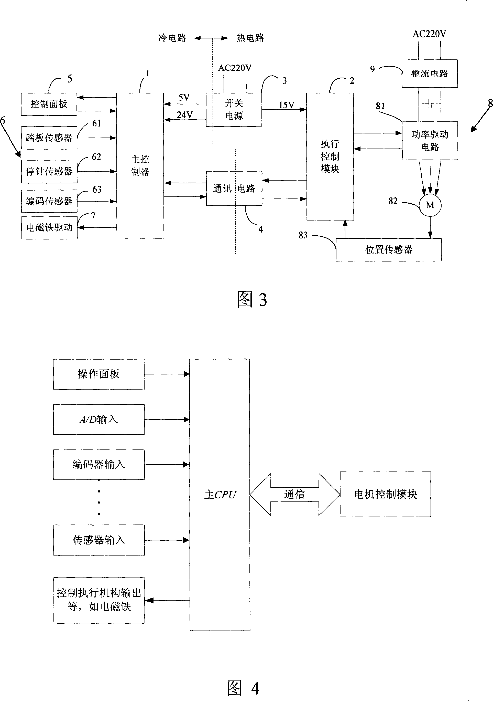
[0036] Please refer to Fig. 3, the novel computerized sewing machine control system includes: a main controller 1, an executive control module 2, a switching power supply 3, a communication circuit 4, a control panel 5, a pedal sensor 61, a needle stop sensor 62, and an encoding sensor 63 The sensor assembly 6, the electromagnet drive circuit 7, the motor power drive circuit 8 and the rectification circuit 9 composed of the power drive circuit 81, the motor 82 and the position sensor assembly 83 are formed.

[0037] The main controller 1 is bidirectionally connected with the control panel 5, and the input ends of the main controller 1 are respectively connected with the output ends of the pedal sensor 61, the needle stop sensor 62, and the encoder sensor 63; the output of the pedal sensor controls the speed of the sewing machine and the operation of each actuator Information; the needle stop position sensor is used to feedback the position of the sewing machine needle.

[0038...


PUM


Abstract

The present invention relates to a new-type computer sewing machine control system. It includes controller, control panel, treadle sensor, needle-stopping sensor, electromagnet drive circuit, motor and commutating circuit. It is characterized by that the described controller is composed of main controller, executive control module, communication circuit respectively connected with main controller and executive control module and switch power supply. Besides, said invention also includes a motor power drive circuit and a position sensor component and also provides the connection mode of above-mentioned all the portions.

Description

technical field [0001] The invention relates to a control circuit arranged on a sewing machine to control the operation of the sewing machine, in particular to a novel computerized sewing machine control system. Background technique [0002] In the prior art, the drive control of a traditional industrial sewing machine generally uses a clutch motor, which is an asynchronous motor that runs continuously after being powered on, and relies on the clutch to drive the sewing machine head to run. This drive control method has the advantages of large power consumption and bulky volume. , Noise, poor speed control and other shortcomings. [0003] Please refer to Fig. 1, the control circuit of another industrial sewing machine A10 driven by an electronic motor in the prior art consists of a controller A1, a control panel A2 connected to the controller A1, an induction motor A3, a clutch A4, three It is composed of automatic electromagnet A5, synchronous sensor A6 and pedal sensor A7...

Claims


Application Information

Patent Timeline
IPC IPC(8): D05B69/00
Inventor 甄力林茂峰张恒耿冯祖明朱兰斌
Owner SHANGHAI POWERMAX TECH INC
Why Eureka
Try Eureka