Method for showing latent fingerprint, and develop system
A fingerprint, a potential technology, applied in chemical instruments and methods, measuring devices, material analysis through optical means, etc., can solve the problems of low-energy radioactivity of uranyl zinc acetate, interference with fingerprint fluorescence, fingerprints are not easy to show, etc., to achieve retention time Long, strong fluorescent effect, and simple equipment
- Summary
- Abstract
- Description
- Claims
- Application Information
AI Technical Summary
Problems solved by technology
Method used
Image
Examples
Embodiment 1
[0038] The first step is to manufacture and synthesize the red CdTe fluorescent nanoparticle solution. The chemical reaction equation followed by the selected raw materials is:
[0039] a) Te+NaBH 4 +H 2 O→NaHTe+Na 2 B 4 o 7 +H 2 ↑
[0040] b) NaHTe+CdCl 2 →CdTe+NaCl
[0041] Dissolve 29 mg of CdCl in a three-neck flask 2 2.5H 2 0 and 25 μl of thioglycolic acid in 100 ml of water, adjust the pH value to 11 with NaOH, pass argon gas through the mouth of the three-necked flask side, and evacuate the air in the three-necked flask. Add 50mg NaBH to another reaction vial 4 and 26mg of tellurium powder, reacted for 2-3 hours under stirring, and then poured it into a three-necked flask. Then pour the mixed aqueous solution in the three-neck flask into a quartz microwave reaction tube, program the temperature to 80° C., and continue heating for 120 minutes to obtain a red fluorescent nanoparticle solution.
[0042] In the second step, take the aluminum foil with potential ...
Embodiment 2
[0047] The first step is to manufacture and synthesize the yellow CdTe fluorescent nanoparticle solution. The chemical reaction equation followed by the selected raw materials is:
[0048] a) Te+NaBH 4 +H 2 O→NaHTe+Na 2 B 4 o 7 +H 2 ↑
[0049] b) NaHTe+CdCl 2 →CdTe+NaCl
[0050] Dissolve 29 mg of CdCl in a three-neck flask 2 2.5H 2 0 and 25 μl of thioglycolic acid in 100ml of water, adjust the pH to 11 with NaOH, pass argon gas through the mouth of the three-necked flask side, and empty the air in the three-necked flask. Add 50mg NaBH to another reaction vial 4 and 26mg of tellurium powder, reacted for 2-3 hours under stirring, and then poured it into a three-necked flask. Then pour the mixed aqueous solution in the three-necked flask into a quartz microwave reaction tube, program the temperature to 80° C., and continue heating for 30 minutes to obtain a yellow fluorescent nanoparticle solution.
[0051] In the second step, take the glass with potential fingerprint...
Embodiment 3
[0056] The first step is to manufacture and synthesize the red CdTe fluorescent nanoparticle solution. This step is the same as the first step in Example 1 and will not be repeated here.
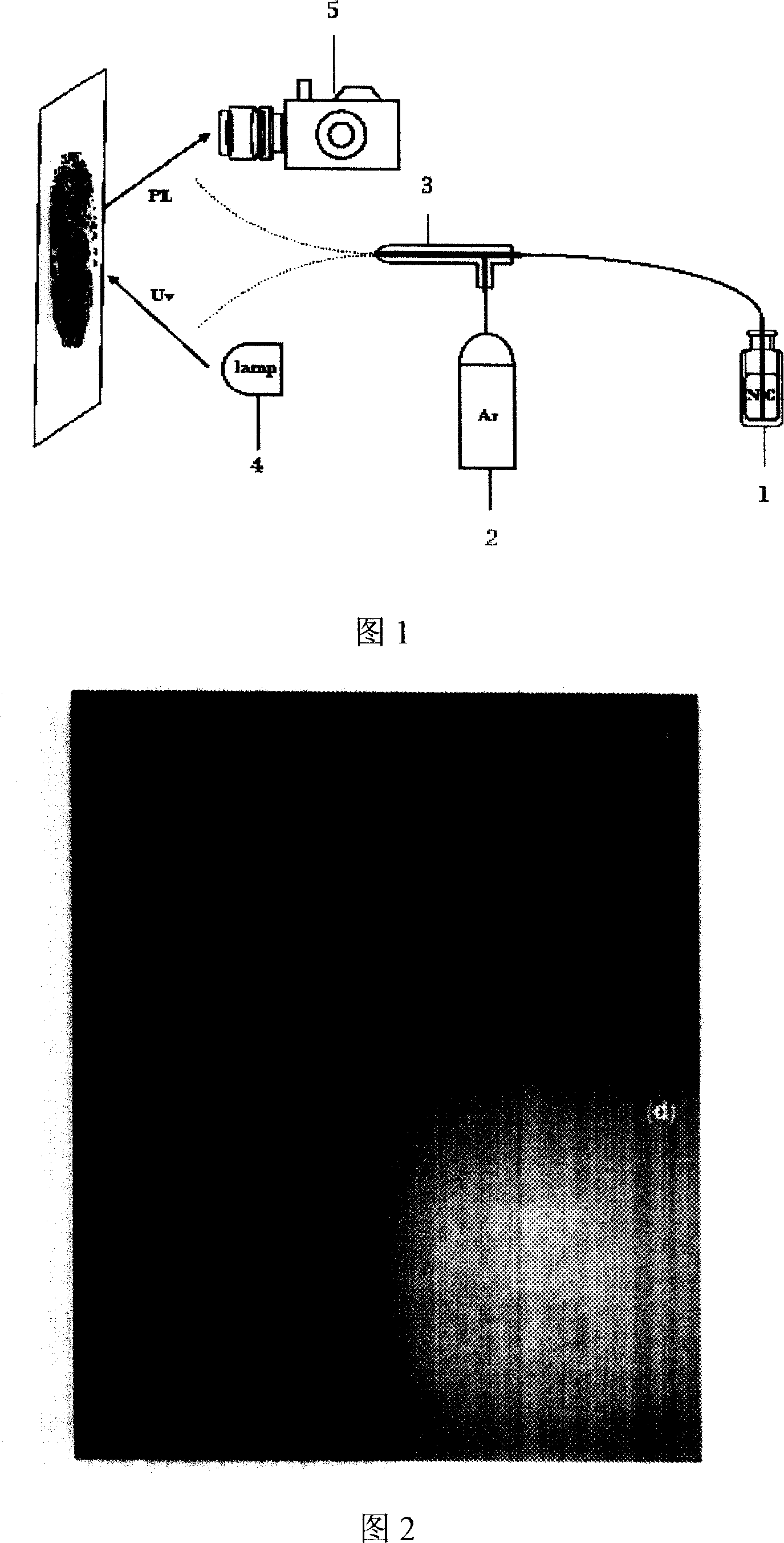
[0057] In the second step, take the plastic beverage bottle with potential fingerprints and place it, and inject the CdTe red fluorescent nanoparticle solution synthesized in the first step into container 1, the air inlet of the D-type ICP glass high-efficiency atomizer Connect the gas outlet of the argon cylinder 2 with a plastic tube, and connect the inlet of the D-type ICP glass high-efficiency atomizer 3 with the outlet of the container 1 containing the CdTe red fluorescent nanoparticle solution with a plastic tube, and adjust the argon gas to enter According to the air intake of D-type ICP glass high-efficiency nebulizer 3 and the distance between D-type ICP glass high-efficiency nebulizer and the plastic beverage bottle with potential fingerprints, turn on the argon gas switch, and pass...
PUM
 Abstract
Description
Claims
Application Information
 - R&D
- Intellectual Property
- Life Sciences
- Materials
- Tech Scout
- Unparalleled Data Quality
- Higher Quality Content
- 60% Fewer Hallucinations
Browse by: Latest US Patents, China's latest patents, Technical Efficacy Thesaurus, Application Domain, Technology Topic, Popular Technical Reports.
© 2025 PatSnap. All rights reserved.Legal|Privacy policy|Modern Slavery Act Transparency Statement|Sitemap|About US| Contact US: help@patsnap.com


