Servomotor current control method and servomotor

A current control, servo motor technology, applied in the field of servo motors, can solve the problems of motor energy efficiency deterioration and large ineffective current, and achieve the effects of simplifying structure, improving energy efficiency, and cheap manufacturing

Inactive Publication Date: 2007-08-01
TOSHIBA MASCH CO LTD
View PDF1 Cites 7 Cited by
  • Summary
  • Abstract
  • Description
  • Claims
  • Application Information

AI Technical Summary

Problems solved by technology

[0009] However, in Patent Document 1, under such circumstances, a large reactive current Id continues to flow in the negative direction.
Since the useless current continues to flow in this way, unnecessary heat will continue to be generated that should not be generated. Therefore, additional compensation measures must be taken in the maintenance and management of the motor. In addition, various problems such as deterioration of the energy efficiency of the motor will occur.

Method used


Image

  • Servomotor current control method and servomotor
  • Servomotor current control method and servomotor
  • Servomotor current control method and servomotor

Examples


no. 1 approach

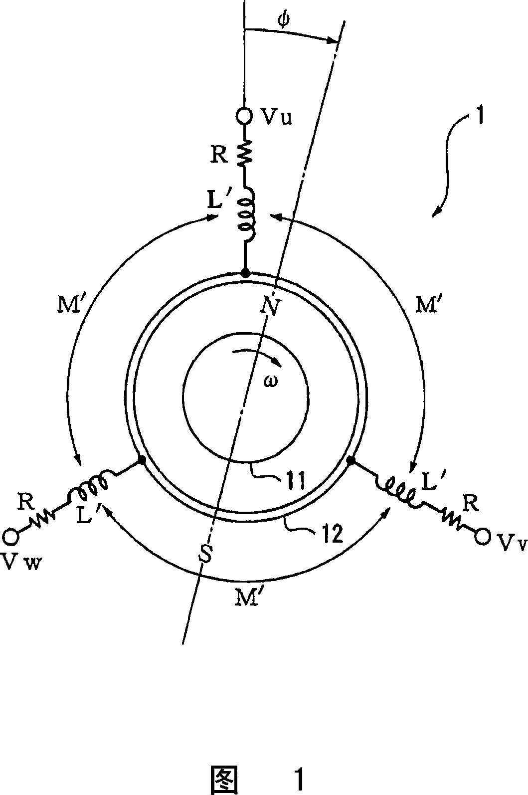
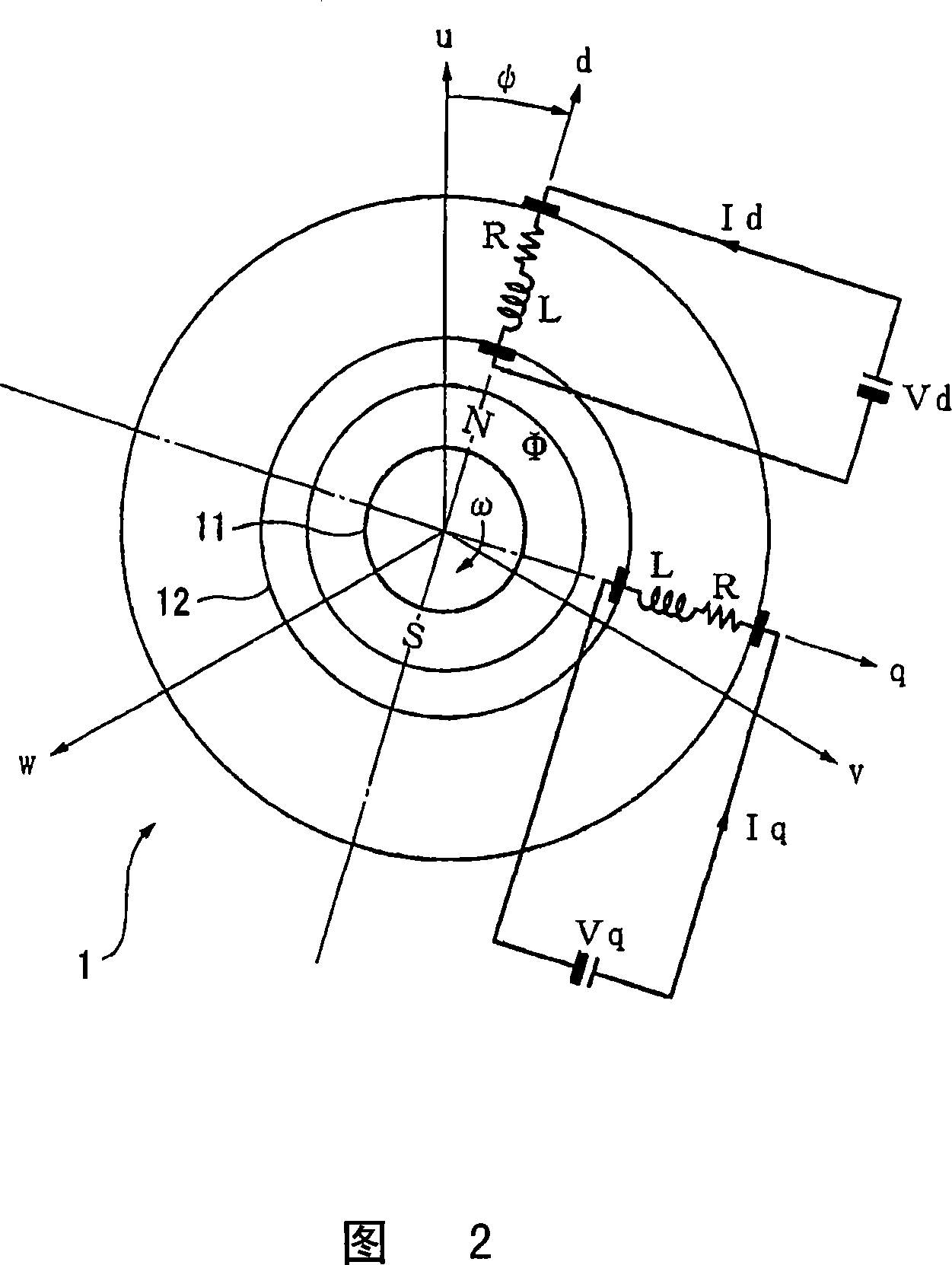
[0051] FIG. 1 is an equivalent circuit diagram of a servo motor 1 according to the first embodiment of the present invention.

[0052] The servo motor 1 is a three-phase synchronous motor having a magnetic field 11 composed of permanent magnets and an armature 12 having three-phase (u, v, w-phase) armature coils. The magnetic field 11 is set to be able to rotate as a rotor. If alternating currents (armature currents) having a phase difference of 120° flow through the phases of the armature 12 as the stator, armature magnetic flux rotating at the same frequency as the alternating current can be generated. The magnetic field 11 receives a magnetic force that makes its own field magnetic flux parallel to the rotating armature magnetic flux, so it rotates following the rotating armature magnetic flux (rotation angle φ, rotation angular velocity ω=dφ / dt. If not specifically limited below, then Assume that ω≥0). In this way, rotational power is generated in the servo motor 1.

[0053] I...

no. 2 approach

[0098] Next, the second embodiment will be described.

[0099] The following avoids repetitive descriptions of matters that have been described in the first embodiment. Therefore, each structural element that is the same as or corresponding to each structural element of the first embodiment is assigned the same reference numeral, and the description thereof is omitted or simplified.

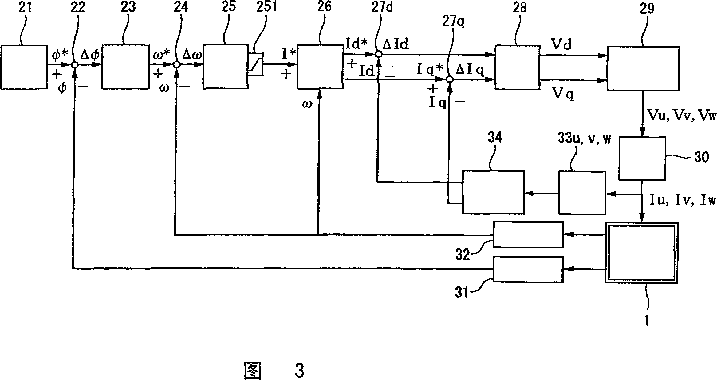
[0100] In this embodiment, the limiter 251 in FIG. 3 is not provided. Since there is no limiter 251, the temporary current command I* from the speed controller 25 as the temporary current commander of the present invention is input to the calculator 26 as it is. In addition, in the first embodiment, I* is called the "total" current command, but in this embodiment, as described later, I* does not specify the total current of the armature 12, so "tentative" Instead of "total", call it "temporary current command". Here, the addition of “tentative” is to consider that I* is used to generate a direct curr...


PUM


Abstract

The invention discloses a servomotor current control method and servomotor. Since, during a light load operation, the produced torque is small and the overall current command I* given to the armature of a servomotor is small, the magnitude in the negative direction of a reactive current command Id* determined by Id*=-|I*|sin theta is small. Therefore, during a light load operation, the overall current flowing through the armature can be small, and production of wasteful heat can be suppressed. During a heavy load operation, since the q-axis current Iq for producing the torque is large, voltage saturation is liable to occur. However, simultaneously with this, the overall current command I* is large during a heavy load operation, and Id* is large in the negative direction. Therefore, a large reactive current Id can be made to flow in the negative direction, and voltage saturation during a heavy load operation can be effectively prevented.

Description

Technical field [0001] The invention relates to a current control method of a servo motor and a servo motor. More specifically, it relates to a current control method for preventing voltage saturation of a servo motor by flowing a negative inactive current Id through an armature that has been subjected to dq conversion, and a servo motor provided with a structure for implementing the current control method. Background technique [0002] In the past, in AC servo motors, in order to prevent voltage saturation, a negative d-axis current Id was flowed on an armature that was subjected to a dq conversion that took the d-axis direction as the magnetic flux direction (for example, refer to Patent Document 1) . In an AC servo motor, unlike the effective current flowing through the q-axis current Iq for generating the rotational torque, Id is an inactive current that has nothing to do with the generated torque. However, by passing Id, the influence of the back electromotive force generate...

Claims


Application Information

Patent Timeline
Patent Type & Authority Applications(China)
IPC IPC(8): H02P21/00H02P27/04H02P27/06H02P21/22H02P23/16H02P23/18
CPCH02P21/06H02P21/02H02P21/0035H02P2207/05H02P21/22H02P21/00
Inventor 胜又和浩伊东隆充
Owner TOSHIBA MASCH CO LTD
Why Eureka
Try Eureka