Multi-source metal ion implantation machine

A metal ion implantation and metal ion source technology, applied in the field of multi-source metal ion implanters, can solve the problems of complex structure, long time required, energy loss, etc., and achieve the effect of uniform ion implantation, short implantation time and simple structure

Inactive Publication Date: 2007-08-15
珠海市恩博金属表面强化有限公司
View PDF1 Cites 3 Cited by
  • Summary
  • Abstract
  • Description
  • Claims
  • Application Information

AI Technical Summary

Problems solved by technology

The applicant submitted an invention patent application titled "a metal ion implanter" on September 13, 2004, with the patent application number 200410051332.9. The ion implanter of this application has a simple structure, low cost, easy operation and reliable use. However, this machine mainly relies on the rotation of the workpiece target platform to expose the surface of the workpiece (that is, mechanical scanning) for ion implantation, which requires the workpiece target platform to have high flexibility. This method has the following shortcomings: 1. Rotating target It is not a panacea, and it cannot strictly separate the surface of the workpiece that needs to be injected from the surface that does not need to be injected, thus causing unnecessary energy loss and an increase in the temperature of the workpiece; 2. It is difficult for the rotating target to accurately determine the surface of the multi-surface workpiece to be injected 3. Use a normal size ion beam to implant the workpiece. Since the workpiece has multiple surfaces, it takes a long time to complete the implantation and the efficiency is low; 4. The rotating target with relatively complete functions requires multi-dimensional movement. Therefore, the structure is complicated, the cost is expensive, and the work reliability is poor.

Method used


Image

  • Multi-source metal ion implantation machine
  • Multi-source metal ion implantation machine
  • Multi-source metal ion implantation machine

Examples


Embodiment Construction

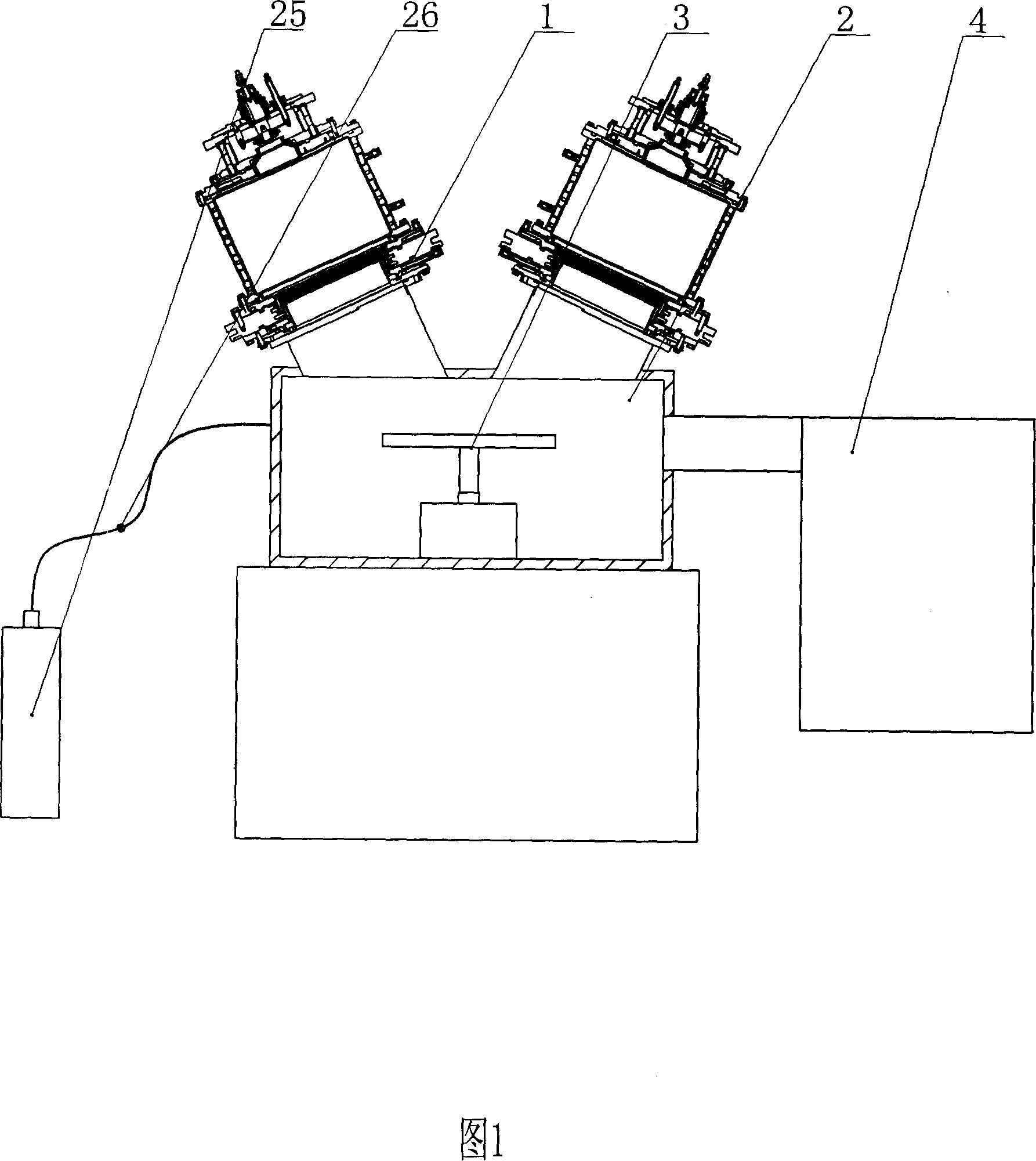
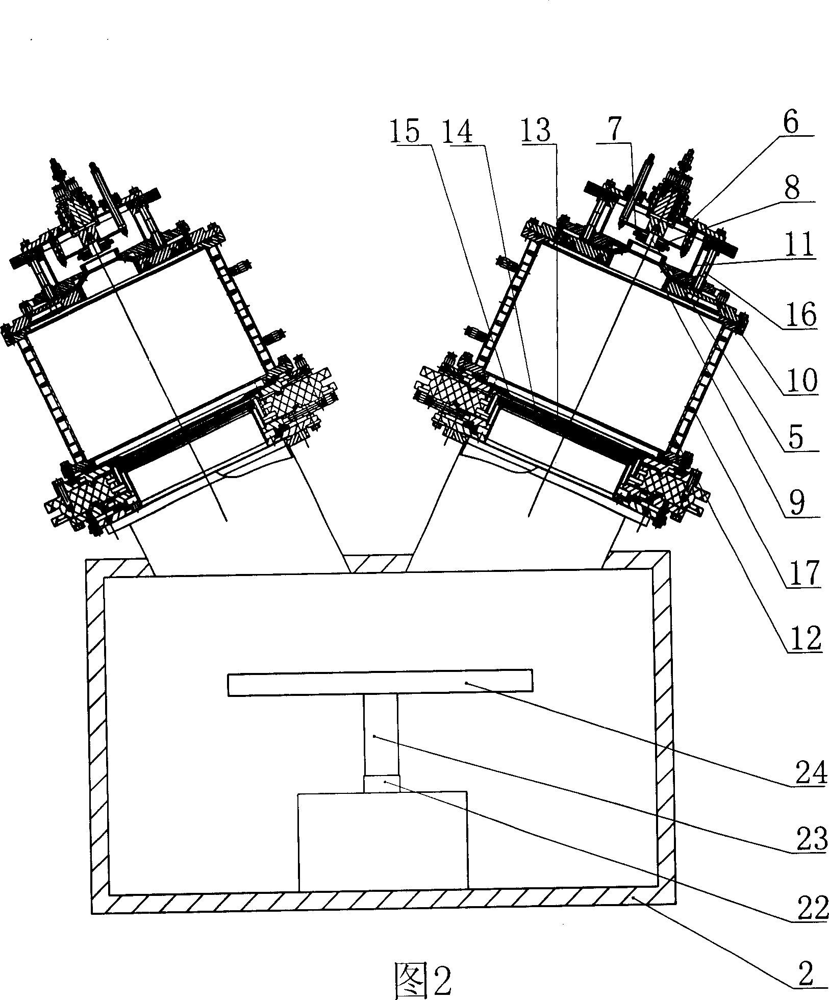
[0018] As shown in Figures 1 and 2, the present invention includes a metal ion source 1, an ion source power supply system, a vacuum chamber 2, a workpiece target platform 3, a motor 22, a vacuum system 4, a cooling system, a nitrogen source 25, and a mass flow valve 26 and control screen.

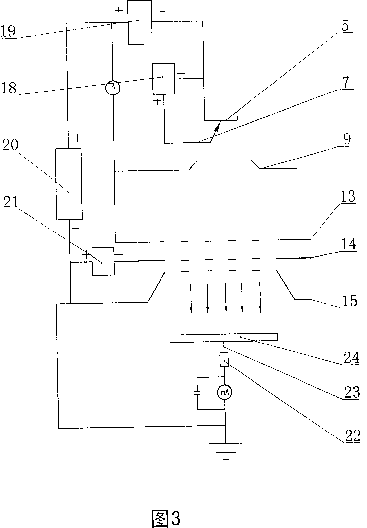
[0019] There are two metal ion sources 1 arranged on the upper part of the vacuum chamber 2 and communicated with the vacuum chamber 2, and the two metal ion sources 1 form an angle of 24 degrees with the vertical direction respectively. The metal ion source includes a cathode 5, a cathode support 6, a trigger electrode 7, an insulating cathode casing 8, an anode 9, an anode support 10, a discharge chamber 11, a plasma chamber 12, a first grid 13, and a second grid 14. The trigger electrode 7 is separated from the insulated cathode sleeve 8 and placed on the outer periphery of the cathode 5. The upper end of the discharge chamber 11 is connected to the cathode support 6, and the lower end ...


PUM


Abstract

The invention discloses a multi-source metallic ion injector, which comprises the following parts: two or more angularly metal ion source (1), ion source electric power system, vacuum chamber (2), work-piece target bench (3), pumped vacuum system (4), cooling system and control panel, wherein the metal ion source (1) includes negative pole (5), negative pole support (6), trigger electrode (7), insulating negative pole sleeve (8), anode (9), anode support (10), arc chamber (11), plasma body chamber (12), first grid (13), second grid (14) and third grid (15).

Description

technical field [0001] The invention relates to a multi-source metal ion implanter. Background technique [0002] Conventional surface treatment technology, because it needs to be carried out in a high temperature environment, will change the overall size and surface finish of the workpiece, so that it needs to be finished after heat treatment, so it cannot meet the requirements of use, and the heat treatment layer is prone to surface peeling and peeling phenomenon. [0003] Ion implantation technology is a high-tech material surface modification developed internationally in recent years. Its basic principle is: use an ion beam with an energy of tens to hundreds of keV to enter the material, the ion beam and the material A series of physical and chemical interactions will occur in the atoms or molecules in the material, and the incident ions will gradually lose energy, and finally stay in the material, causing changes in the surface composition, structure and properties of ...

Claims


Application Information

Patent Timeline
IPC IPC(8): C23C14/48
Inventor 陶士慧马山明邵先华叶围洲蔡恩发蔡坚将吴观绵吴九妹蔡秀芳
Owner 珠海市恩博金属表面强化有限公司
Why Eureka
Try Eureka