Method of decreasing release of nitrogen oxide in the pulverized-coal fired boiler and its used boiler
A nitrogen oxide, pulverized coal boiler technology, applied in the field of boilers, can solve the problems of low denitrification rate and high operation cost, and achieve the effect of high denitrification rate and low operation cost
- Summary
- Abstract
- Description
- Claims
- Application Information
AI Technical Summary
Problems solved by technology
Method used
Image

Examples
specific Embodiment approach 1
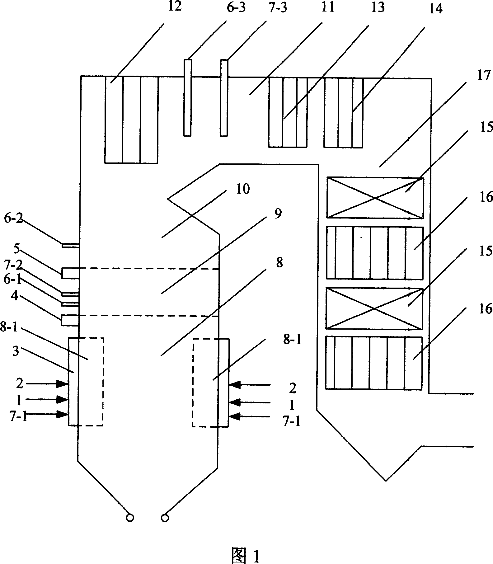
[0008] Specific Embodiment 1: This embodiment is described in conjunction with FIG. 1. This embodiment is divided into a main combustion zone 8, a reduction zone 9, a burnout zone 10, an area near the burner 8-1, a horizontal flue 11 and a tail flue 17. The pulverized coal boiler; the amino reducing agent is sprayed into the reduction zone 9, the burnout zone 10 and the horizontal flue 11; the hydrocarbon-based reducing agent is sprayed into the main combustion zone 8 and the reduction zone 9 or the main combustion zone 8, The reduction zone 9 and the horizontal flue 11; the area near the burner 8-1 is an oxidizing atmosphere, and the excess air coefficient at the outlet of the main combustion zone 8 is controlled by air distribution to 0.8-0.95, and the excess air coefficient at the outlet of the reduction zone 9 is 0.9-1 , The excess air coefficient at the outlet of the burnout zone 10 is 1.15 to 1.2; the total amount of injection of the amino reducing agent is 1 to 1.6 times...
specific Embodiment approach 2
[0010] Specific embodiment two: this embodiment is described in conjunction with Fig. 1, and the difference between this embodiment and specific embodiment one is: the amino reducing agent is injected in three stages, and the first stage amino reducing agent is injected from the primary burn-off air nozzle 4 or The primary nozzle 6-1 of the amino reducing agent is sprayed into the reduction zone 9; the second-level amino reducing agent is sprayed into the burnout zone 10 from the secondary burn-off air nozzle 5 or the secondary nozzle 6-2 of the amino reducing agent; The reducing agent is sprayed into the horizontal flue 11 from the third-stage nozzle 6-3 of the amino reducing agent; the injection amount of the first-stage amino reducing agent is 20% to 40% of the total injection amount of the amino reducing agent, and the second-stage amino reducing agent The injected amount of the amino reducing agent is 20%-40% of the total injected amount of the amino reducing agent, and th...
specific Embodiment approach 3
[0011] Specific embodiment three: This embodiment is described in conjunction with Fig. 1. The difference between this embodiment and specific embodiment two is: the first-stage amino reducing agent is sprayed into the reduction zone 9 from the primary over-burning air nozzle 4; the second-stage amino The reducing agent is sprayed into the burnout zone 10 from the secondary burnout air nozzle 5 . Others are the same as the second embodiment.
[0012] In this embodiment, the amino reducing agent enters the furnace through the overburning air nozzle, which can improve the mixing effect of the amino reducing agent and the furnace flue gas, and is beneficial to improve the denitrification rate.
PUM
 Abstract
Description
Claims
Application Information
 - R&D
- Intellectual Property
- Life Sciences
- Materials
- Tech Scout
- Unparalleled Data Quality
- Higher Quality Content
- 60% Fewer Hallucinations
Browse by: Latest US Patents, China's latest patents, Technical Efficacy Thesaurus, Application Domain, Technology Topic, Popular Technical Reports.
© 2025 PatSnap. All rights reserved.Legal|Privacy policy|Modern Slavery Act Transparency Statement|Sitemap|About US| Contact US: help@patsnap.com