Permanent magnet polarized external rotor radial magnetic bearing

A technology of permanent magnetic bias and magnetic bearings, applied in the direction of bearings, shafts and bearings, shafts, etc., can solve the problems of large excitation current, large axial length and volume, unfavorable control, etc., achieve low loss characteristics, shorten axial The effect of distance, avoiding coupling

Inactive Publication Date: 2007-08-29
BEIHANG UNIV
View PDF6 Cites 10 Cited by
  • Summary
  • Abstract
  • Description
  • Claims
  • Application Information

AI Technical Summary

Problems solved by technology

Some of the current radial magnetic bearing structures for permanent magnet bias outer rotors are based on ordinary radial electromagnetic bearings, and permanent magnets are placed on the electromagnetic magnetic circuit, so that the magnetic flux generated by the control coil must pass through the permanent magnets. The magnetic reluctance of the magnet is very large, so the control coil needs a large excitation current to generate a certain electromagnetic flux, which will obviously increase the power consumption of the bearing; some structures directly connect the permanent magnet to the stator lamination core, so that the permanent magnet When the circuit passes through the stator core vertically, it will lose too much magnetomotive force, which will greatly weaken the attraction force of the permanent magnet to the rotor shaft; Laminated iron core forms a circuit, Chinese patent application number: 200510011270.3 and 200510011690.1 structure permanent magnet bias outer rotor radial magnetic bearing, as shown in Figure 1 and Figure 2, the permanent magnet magnetomotive force will not generate loss in the laminated iron core At the same time, the electric excitation magnetic circuit will not pass through the permanent magnet itself, but the axial length is longer due to the need to use it in pairs, so it cannot meet the small size and light weight requirements of spacecraft such as satellites and space stations.
If the excitation coils at both ends of the two magnetic bearing structures are separately controlled in order to shorten the axial length, that is, one radial magnetic bearing is used as two magnetic bearings, then the electromagnetic flux generated by the excitation coils at both ends of the magnetic bear

Method used


Image

  • Permanent magnet polarized external rotor radial magnetic bearing
  • Permanent magnet polarized external rotor radial magnetic bearing
  • Permanent magnet polarized external rotor radial magnetic bearing

Examples


Example Embodiment

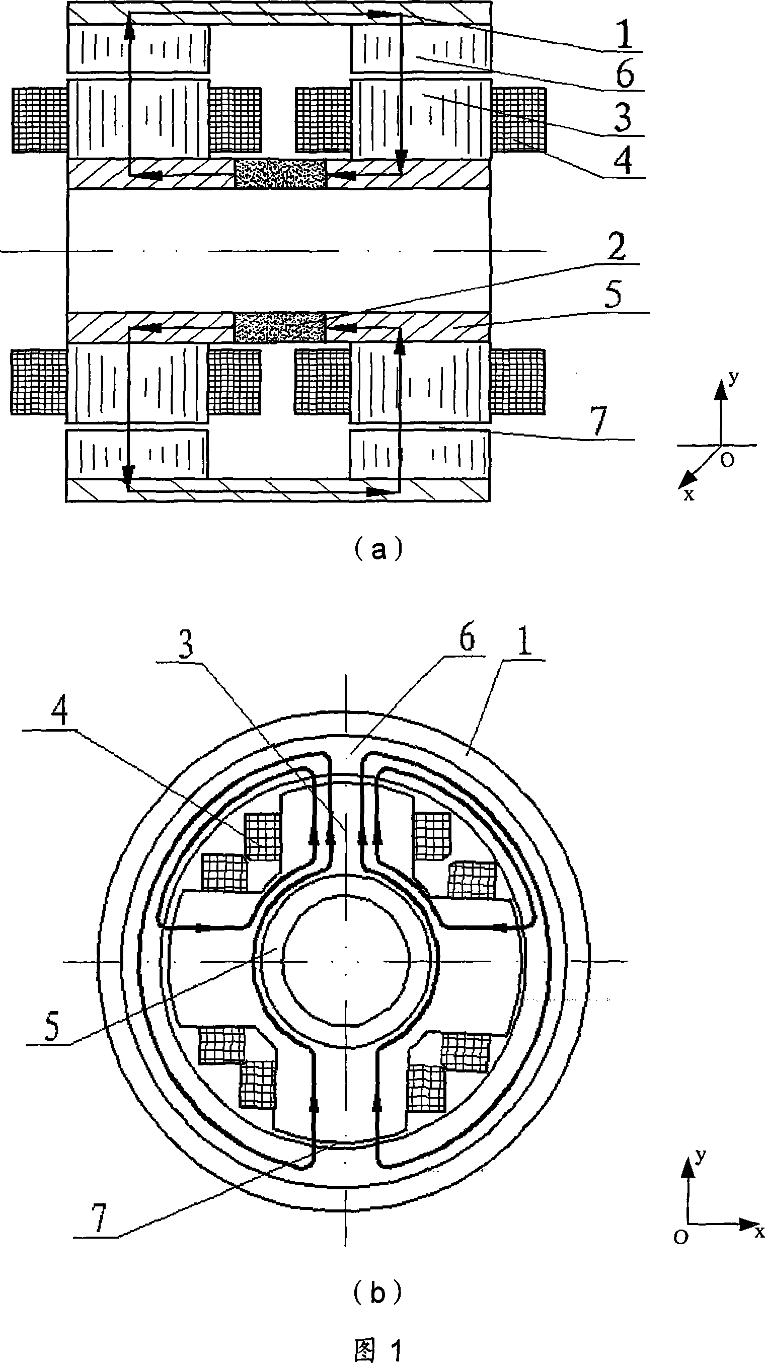
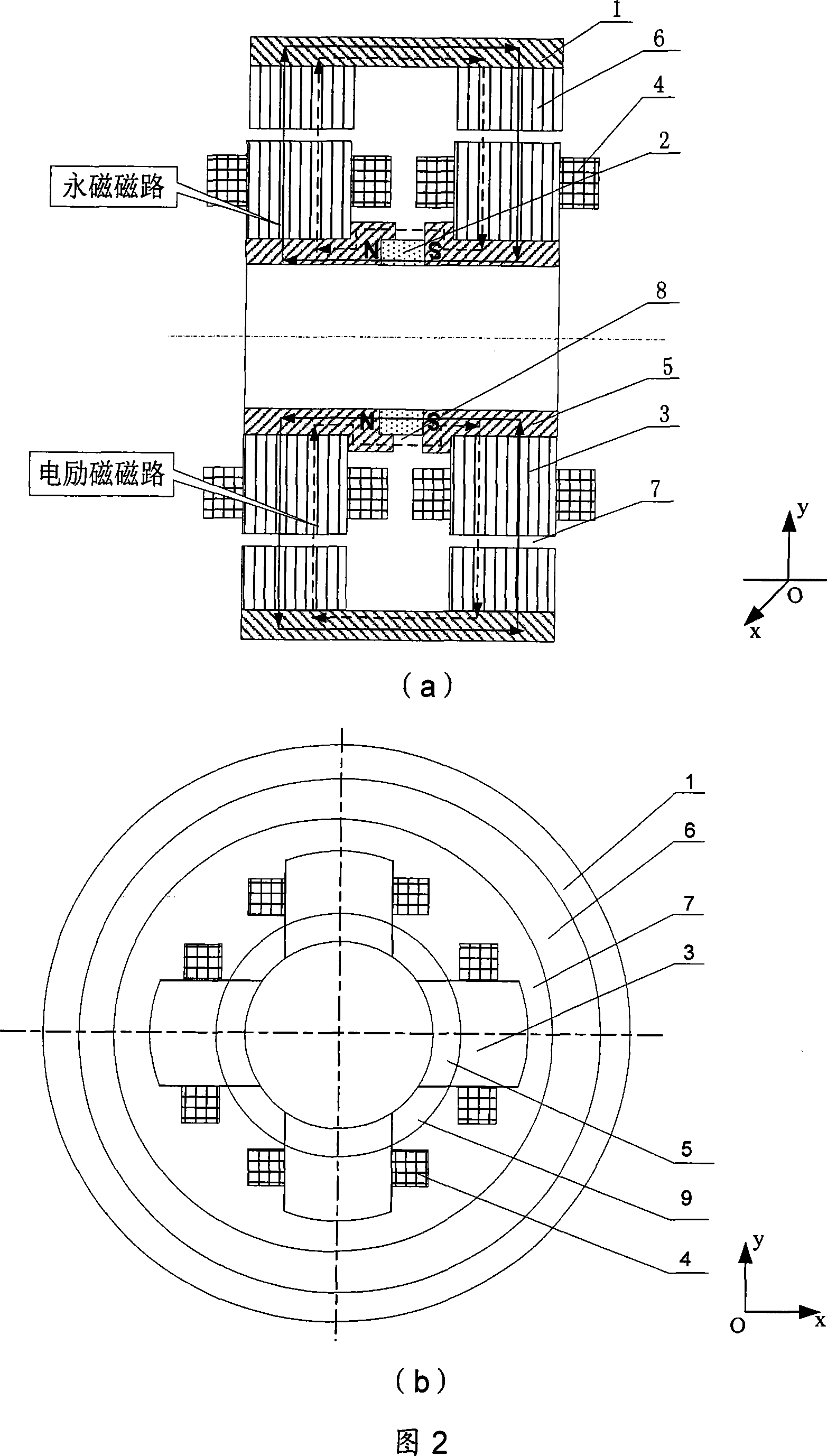
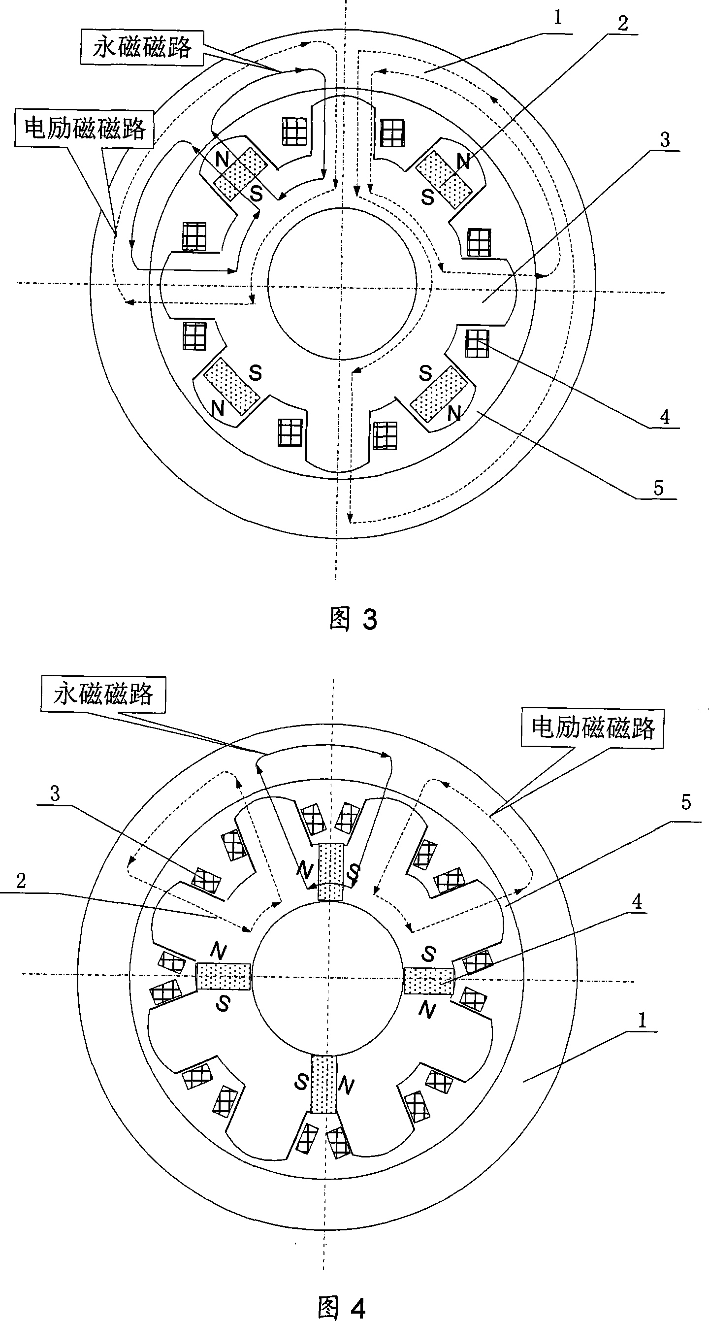
[0016]As shown in Figures 1 and 2, the present invention is generally composed of left, middle and right groups of stators and rotors, including three inner magnetic permeable rings: inner magnetic permeable ring I1, inner magnetic permeable ring II12 and inner magnetic permeable ring III14 , 2 permanent magnets: permanent magnet I13 and permanent magnet II16, 3 stator cores: stator core I2, stator core II11 and stator core III15, 8 excitation coils 3, 4 rotor cores: rotor core I4, rotor core II6, Rotor iron core III8 and rotor iron core IV10, 2 outer magnetic conductive rings: outer magnetic conductive ring I5 and outer magnetic conductive ring II9, 1 outer magnetic isolation ring 7, 12 air gaps 17. A certain gap is left between the inner surface of the rotor core and the outer surface of the stator core to form an air gap 17, and the gap is generally in the range of 0.2mm to 0.3mm. The stator iron core I2, stator iron core III15 and stator iron core II11 respectively form 12...


PUM


Abstract

The invention is a permanent magnet biasing inner rotor radial magnetic bearing, comprising inner magnetic conductor rings, stator iron cores, rotor iron cores, outer magnetic conductor rings, outer magnetic isolation rings, permanent magnet, excitation coils, and air gaps, where the stator iron cores I and II compose 8 magnetic poles in the positive and negative directions of X and Y axes at the left and right ends, each magnetic pole is wound with excitation coil, the inner magnetic conductor ring is inside the stator iron core, the rotor iron cores I and IV are outside the stator iron cores I and II, respectively; the rotor iron core II, the outer magnetic isolation ring, and the rotor iron core III are outside in the stator iron core III; the rotor iron cores I and II are interconnected through the outer magnetic conductor ring I; the rotor iron cores III and IV are interconnected through the outer magnetic conductor ring II; the outer magnetic conductor rings I and II are connected with the rotor iron cores II and III through the outer magnetic isolation ring, respectively; the air gaps are between the rotor iron cores and the stator iron cores; the inner magnetic conductor rings II and III are interconnected through the permanent magnet I, and the inner magnetic conductor rings III and I are interconnected through the permanent magnet II. And the invention can replace the existing magnetic bearings used in pairs, largely shortening axial distance.

Description

technical field [0001] The invention relates to a non-contact magnetic suspension bearing, in particular to a radial magnetic bearing with a permanent magnetic bias outer rotor, which can be used as a non-contact support for rotating parts in mechanical equipment such as a magnetic suspension flywheel, a magnetic suspension control moment gyroscope, a motor, and a machine tool. Background technique [0002] Magnetic suspension bearings are divided into pure electromagnetic bearings and hybrid magnetic suspension bearings with permanent magnetic bias and electromagnetic control. The former uses large current and consumes a lot of power, and the hybrid magnetic suspension bearings with permanent magnetic bias and electromagnetic control. The magnetic field generated by the permanent magnet bears the main load. Bearing capacity, the electromagnetic field provides auxiliary adjustment bearing capacity, so this kind of bearing can greatly reduce the control current and reduce the ...

Claims


Application Information

Patent Timeline
IPC IPC(8): F16C32/04
CPCF16C32/0465F16C32/0487F16C2300/20
Inventor 房建成杨磊韩邦成孙津济王曦
Owner BEIHANG UNIV
Why Eureka
Try Eureka