
System integrating air separation with cool capacity recovery of liquefied natural gas

A technology of liquefied natural gas and cold energy recovery, applied in the direction of liquefaction, refrigeration and liquefaction, cold treatment separation, etc., to achieve great social and economic benefits, and reduce energy consumption.

Active Publication Date: 2007-09-12
HANGZHOU HANGYANG
View PDF3 Cites 38 Cited by
  • Summary
  • Abstract
  • Description
  • Claims
  • Application Information

AI Technical Summary

Problems solved by technology

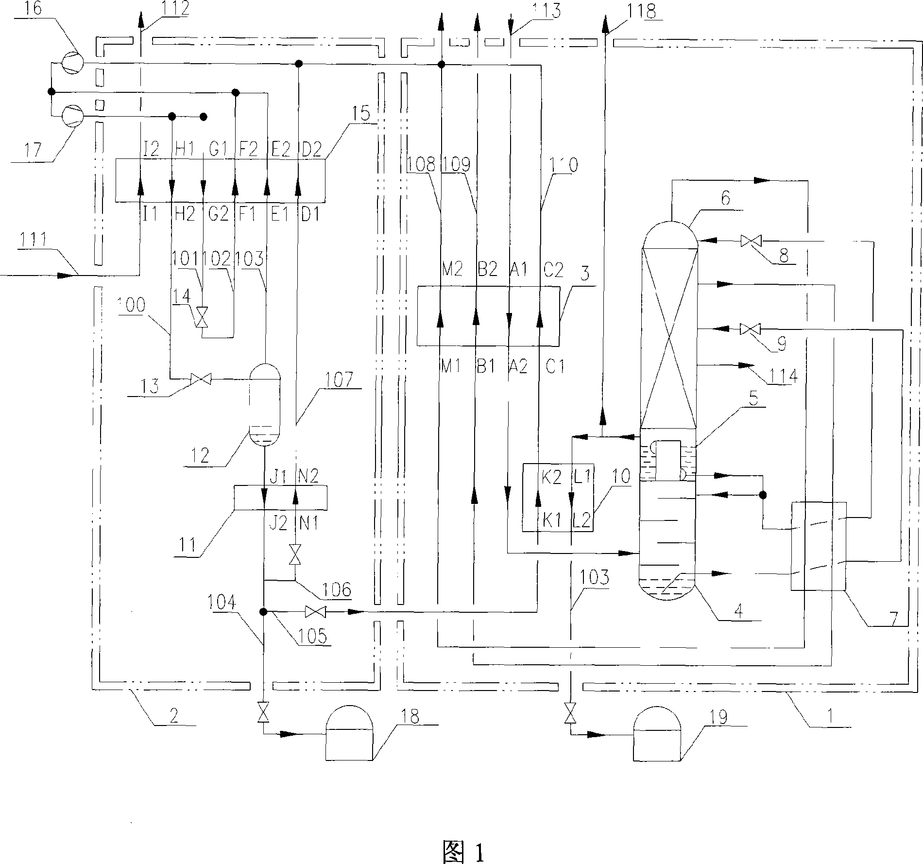
[0009] The purpose of the present invention is to provide an integrated air separation and liquefied natural gas cold recovery system to obtain liquid oxygen, liquid nitrogen and argon fractions with low energy consumption in view of the safety problems existing in the current air separation method and device utilizing the cold capacity of liquefied natural gas and other products

Method used


Image

  • System integrating air separation with cool capacity recovery of liquefied natural gas
  • System integrating air separation with cool capacity recovery of liquefied natural gas
  • System integrating air separation with cool capacity recovery of liquefied natural gas

Examples


Embodiment 1

[0027] Embodiment 1: as shown in Figure 1, the feed air 113 that removes carbon dioxide, water, acetylene and other hydrocarbon impurities is sent into the heat exchange channel A1-A2 of the main heat exchanger 3 in the cold box I1, and other heat exchangers The reflux gas in the hot channel is exchanged for heat, cooled to a suitable fractionation temperature, and sent to the bottom of the fractionation lower tower 4 .

[0028] The main heat exchanger 3, fractionation column and liquid oxygen heat exchanger 10 are located inside the independent cold box I1. The fractionation tower is composed of a fractionation lower tower 4, a fractionation upper tower 6 and a main condensing evaporator 5 connected. The cooled raw material air enters the bottom of the lower fractionation tower 4, and the heat and mass transfer process occurs on the multi-layer trays with the reflux liquid flowing down from the top of the lower fractionation tower 4. Oxygen-enriched liquid air with a higher ...

Embodiment 2

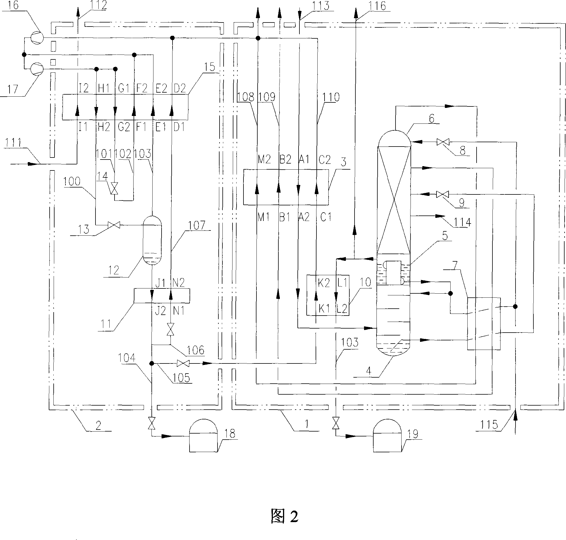
[0041] Example 2. The system and device for separating air by utilizing the cold energy of liquefied natural gas are shown in Figure 2. The difference between this embodiment 2 and the embodiment is that when the supply of liquefied natural gas 111 is insufficient due to an emergency, additional cryogenic liquid can be provided to the device, The cryogenic liquid may be liquid nitrogen.

[0042] When the liquefied natural gas 111 is in short supply due to an emergency, it may be the liquid nitrogen 115 introduced from the outside and sent to the upper fractionation tower. Liquid nitrogen 115 can be directly sent into the fractionation upper tower 6, or can be sent into the fractionation upper tower 6 after being merged with the liquid nitrogen extracted from the fractionation lower tower 4 and passed through the liquid nitrogen liquid-air subcooler 7 and supercooled.

[0043] When the liquefied natural gas 111 is insufficient due to an emergency, the liquid nitrogen 115 intro...

Embodiment 3

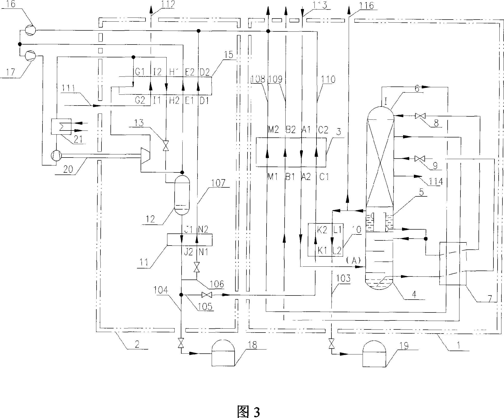
[0044] Example 3. The system and device for separating air by using the cold energy of liquefied natural gas are shown in Figure 3. The difference between this embodiment and Embodiment 1 and Embodiment 2 is that: a booster turbo expander 20 and a water cooler 21 are added. The nitrogen gas coming out from the medium-pressure nitrogen turbine compressor 17 continues to be compressed through the supercharging part of the booster turbo expander 20, which is located outside the cold box II2. After the nitrogen is compressed, it is pre-cooled by the water cooler 21 and divided into two parts. One strand enters the LNG heat exchanger 15, one strand is extracted from the middle of the LNG heat exchanger 15, enters the expansion part of the booster turbo expander 20 to expand and reduce pressure, and merges with the nitrogen gas from the vapor-liquid separator 12 to return to the LNG The heat exchanger 15 reheats and returns to the inlet of the medium-pressure nitrogen turbine compr...


PUM


Abstract

This kind of system separating air and recovering cold energy of liquefied natural gas at least includes an air separator mainly consisting of a fractionating tower and at least includes an equipment for recovering cold energy of liquefied natural gas mainly consisting of an liquefied natural gas heat exchanger, which still includes main heat exchanger, liquid-oxygen heat exchanger and liquid-nitrogen liquid air subcooler; nitrogen drawing out from the underpart of the upper column on the fractionating tower passes through liquid-nitrogen liquid air subcooler and reheated by main heat exchanger, and enters into liquefied-natural-gas heat exchanger to precool and exchange heat; the equipment recovering cold energy of liquefied natural gas at least includes air-liquid separator and liquid nitrogen subcooler, which is placed in a single ice chest II; while main heat exchanger, liquid-oxygen heat exchanger, liquid-nitrogen liquid air subcooler and fractionator consisting of the lower column, the upper column and main evaporator are placed in an ice chest I; it fully utilizes high-grade cooling capacity of liquefied natural gas, and makes energy consumption of air separator reduce notably and ensures it operate safely, and can get the great society and economy benefits.

Description

technical field [0001] The invention relates to a system integrating air separation and cooling recovery of liquefied natural gas, which is especially suitable for mass production of liquid oxygen, liquid nitrogen and argon fractions; The oxygen and nitrogen in the air are separated and finally liquefied under certain conditions, which can greatly reduce the energy consumption of the air separation device. Background technique [0002] Air is a homogeneous multi-component mixed gas, mainly composed of oxygen, nitrogen, and argon, and their volume percentages of air are 20.95%, 78.118%, and 0.932%, respectively. Like other substances, oxygen, nitrogen, and argon have three states: gas, liquid, and solid. They are gaseous at normal temperature and pressure. Under standard atmospheric pressure, oxygen is cooled to 90.188K, nitrogen is cooled to 77.36K, and argon is cooled to 87.29K. They all become liquid respectively, and can become gaseous when heated. The difference betwe...

Claims


Application Information

Patent Timeline
Patent Type & Authority Applications(China)
IPC IPC(8): F25J3/04
CPCF25J1/0234F25J1/0015F25J1/0037F25J1/004F25J1/0045F25J1/0224F25J1/0288F25J3/04224F25J3/0423F25J3/04254F25J3/04272F25J3/04351F25J3/04357F25J3/04412F25J2210/42F25J2210/62F25J2250/42F25J2250/50
Inventor 卢杰毛绍融朱朔元何晖
Owner HANGZHOU HANGYANG
Learn More