Full-automatic measurement device for magnetoelectric properties of magnetoelectric material and measuring method thereof

A technology of magnetoelectric materials and measuring devices, which is applied in the direction of magnetic field measurement, magnetic field size/direction, etc. by using electromagnetic devices, can solve the problems of increasing equipment cost, accuracy, insufficient frequency upper limit, and high cost, so as to improve measurement accuracy , working frequency expansion, cost reduction effect

Inactive Publication Date: 2007-09-12
UNIV OF SCI & TECH BEIJING
View PDF0 Cites 29 Cited by
  • Summary
  • Abstract
  • Description
  • Claims
  • Application Information

AI Technical Summary

Problems solved by technology

Therefore, the measurement of the magnetoelectric response signal of the magnetoelectric material involves weak signal detection, and the precise magnetoelectric measurement equipment must use a lock-in amplifier. Due to the high price of the lock-in amplifier, the cost of the existing magnetoelectric measurement equipment at home and abroad expensive
On the other hand, by α ME =dV / (tdH) It can be seen that the acquisition of magnetoelectric properties requires simultaneous measurement of dV and dH, but each common commercial lock-in amplifier can only perform lock-in amplification processing on the signal of one channel, and cannot measure dV and dH at the same time , so the current common practice at home and abroad is to only measure dV and nominally fix dH[1-2]
In actual measurement, especially when the frequency of the AC magnetic field changes, it is not easy to completely fix dH, so it is impossible to do accurate dynamic monitoring of the magnetic field, and thus it is impossible to obtain accurate magnetoelectric properties
The operating frequency range of the lock-in amplifier is also an important indicator of the measurement capability of the magnetoelectric test system. The operating frequency of the general lock-in amplifier is below 200kHz. If the test conditions exceed this operating frequency range, then the lock-in amplifier cannot be used. Meet the needs of the test, the test cannot be carried out
If you want to expand the test frequency of the equipment, you need a more expensive broadband lock-in amplifier, which will undoubtedly further increase the equipment cost
In addition, the change of the magnetoelectric properties with the applied DC bias magnetic field and the change of the magnetoelectric properties with the frequency of the applied AC magnetic field must be measured separately [1-2]. change in frequency
It can be seen that the existing magnetoelectric measurement equipment at home and abroad is expensive, the accuracy and frequency upper limit are not high enough, and the degree of automation of the measurement process needs to be improved urgently.

Method used


Image

  • Full-automatic measurement device for magnetoelectric properties of magnetoelectric material and measuring method thereof
  • Full-automatic measurement device for magnetoelectric properties of magnetoelectric material and measuring method thereof
  • Full-automatic measurement device for magnetoelectric properties of magnetoelectric material and measuring method thereof

Examples


Embodiment 1

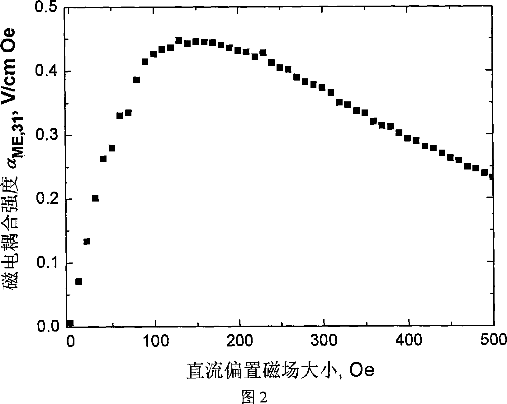
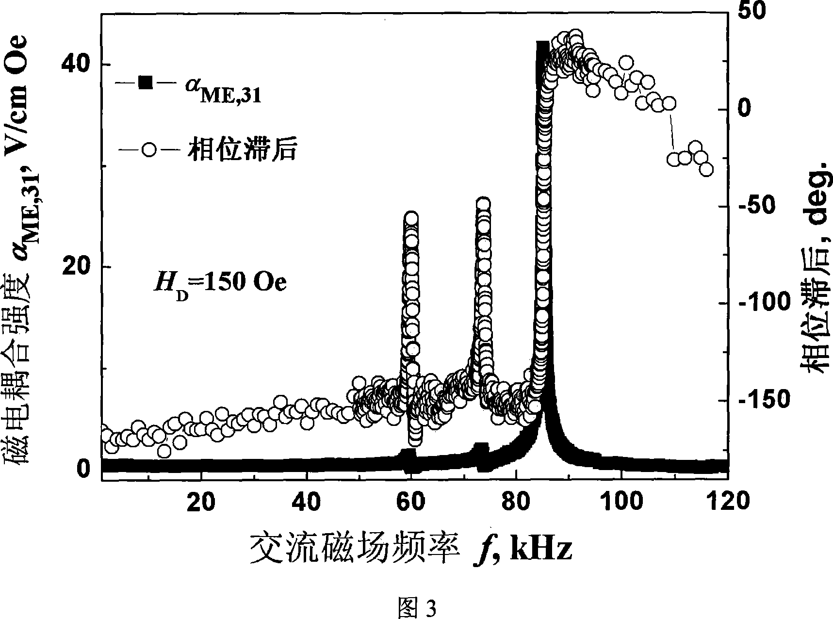
[0027]In embodiment 1, a typical test sample 5 uses a Ni / PZT / Ni layered composite material. Measuring Transverse Magnetoelectric Coupling Coefficient α of Ni / PZT / Ni Layered Composite ME,31 And the corresponding phase lag of magnetoelectricity.

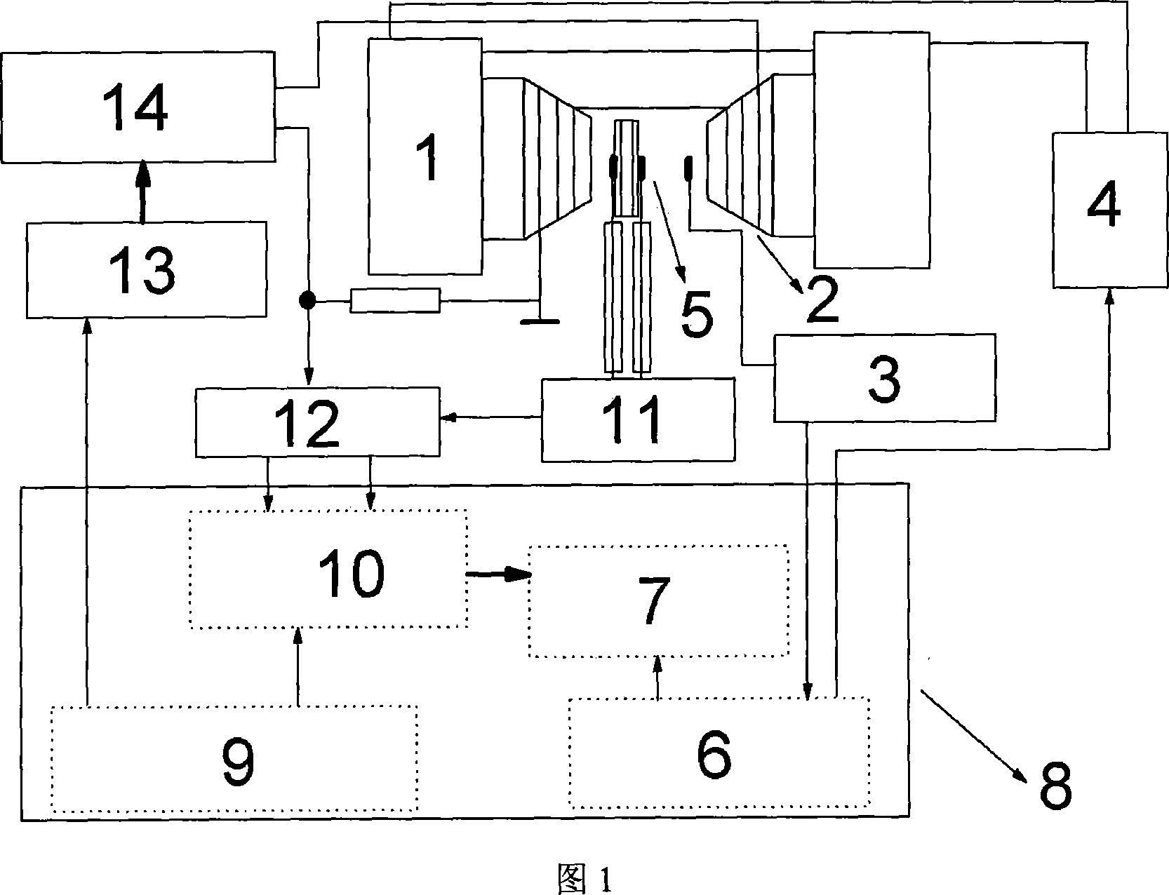
[0028] (1) Assemble the instrument according to the principle of Fig. 1, wherein the sensing resistance R=10Ω for generating the magnetic field. Data acquisition front end 12 is Rigol DS5062CA oscilloscope; signal generator 13 is Agilent 33220A; DC bias magnetic field system uses WWL-LSX21 three-phase DC power supply and SB175 electromagnet; Tesla meter 3 uses HT100; (1.6GHz, 256MB, 40GB, WindowsXP) Install the evaluation version of Labview8.0 as the development platform of the control program. According to the above principles, the corresponding measurement control software is written under Labview.

[0029] (2) The sample tested is a Ni / PZT / Ni layered composite square plate with Ni electroplated on a PZT ferroelectric ceramic with...

Embodiment 2

[0033] Embodiment 2, measuring the transverse magneto-generated electric field coefficient α of Ni / PZT / Ni layered composite material ME,31 and a 3D image of the phase lag of the magnetoelectric response as a function of applied bias magnetic field and applied AC magnetic field frequency.

[0034] (1) In order to increase the magnetic field automatic control module, AD / DA cards (AC6632 and AC6682) are installed in the PCI slot of the computer as the control interface of the DC bias magnetic field, and the hardware and software in the measurement system are correspondingly expanded. The rest are the same as Step 1 in Example 1

[0035] (2) The sample tested is the same as step 2 in Example 1.

[0036] (3) The amplitude of the output AC voltage of the fixed signal generator 13 is 1V, remains unchanged, change the frequency of the signal generator 13 output AC voltage and the size of the DC bias magnetic field (seeing 1 among Fig. 1) simultaneously, run The control program autom...


PUM


Abstract

This invention belongs to magnetic electricity material domain, which conretely relates to using fictitious multichannel phase-locking enlarging principle to implement test material magnetic electricity function method and device of computer control. This invention make phase-locking amplifier fictitious, which is that computer software implements function of phase-locking amplifier. It is very convenient to carry out phase-locking agnification process for random multipath signal by using fictitious phase-locking amplifier. Therefore, it not only precisely automatically survey dE and dH, improve magnetic electricity function measurement precision, but also work frequency limit is boosted a lot compared to hardware phase-locking amplifier, meanwhile decrease manufacture cost of magnetic electricity measuring device. This invention also combines control and measurement of apposition cocurrent offset magnetic field to boost automaticity of magnetic electricity measuring device, thereby improve precision and efficiency of magnetic electricity measurement.

Description

technical field [0001] The invention belongs to the field of magnetoelectric materials, and relates to a measurement technology of magnetoelectric properties of magnetoelectric materials, in particular to a fully computer-controlled device for measuring magnetoelectric properties of magnetoelectric materials and a measurement method thereof realized by using the principle of virtual multi-channel phase-locked amplification. Background technique [0002] Magnetoelectric properties refer to the dielectric polarization of a material induced by an external magnetic field, or the magnetization induced by an external electric field. Generally speaking, the magnetoelectric properties refer to the magnetic field-induced dielectric polarization unless otherwise specified. Magnetoelectric properties have broad application prospects in many high-performance magnetoelectric functional components. Specifically, it can be used in many fields such as magnetic field detection, magnetoelectr...

Claims


Application Information

Patent Timeline
Patent Type & Authority Applications(China)
IPC IPC(8): G01R33/06
Inventor 陆俊潘德安乔利杰
Owner UNIV OF SCI & TECH BEIJING
Why Eureka
Try Eureka