Non-symmetric structure grid velocity compensation method and velocity compensation-type bending coplane waveguide
A technology of coplanar waveguide and speed compensation, which is applied in the microwave field, can solve the problems of volume integration reduction and cost increase, and achieve the effect of reducing process and cost
- Summary
- Abstract
- Description
- Claims
- Application Information
AI Technical Summary
Problems solved by technology
Method used
Image
Examples
Embodiment 1
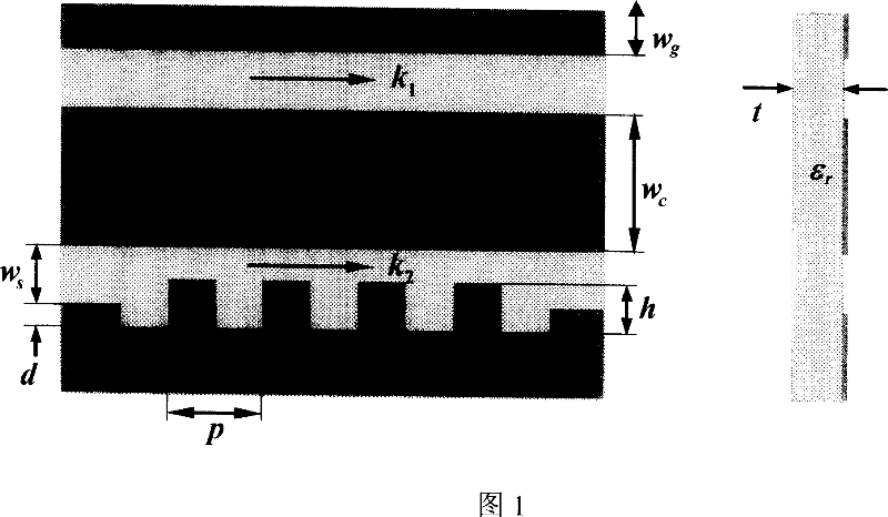
[0037] Embodiment 1: As shown in Figure 1, Figure 1 shows the structure and parameters of the coplanar waveguide grating structure. Different coplanar waveguide grating structures can be obtained by changing its structural parameters. It can be seen from Figure 1 that k 1 and k 2 are the propagation constants of the electromagnetic wave on the non-grid structure and the grid structure, respectively. In order to prove the change of the grid structure to the propagation speed of electromagnetic waves and understand the effect of different structures, the k 2 k 1 ratio, as shown in Table 1. The specific structure is set as follows: w c = 0.25mm, w g = 1 mm, w s = 0.1mm, t = 0.0625mm, ε r =12.9, Z c =50Ω. Among them, Z c is the characteristic impedance of the coplanar waveguide. It can be seen from the table that k 2 / k 1 Both are greater than 1, indicating that the grid structure does have a slow wave effect.
[0038] Table 1 Propagation constant ratio of different ...
Embodiment 2
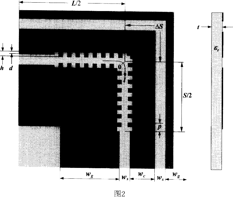
[0043] Embodiment 2: As shown in FIG. 2 , a rectangular grid velocity compensation curved coplanar waveguide.
[0044] When the grid structure in Table 1 is specifically applied to a discontinuous coplanar waveguide, the slot with a shorter path on the coplanar waveguide should be set as a grid structure. Taking the 90° curved coplanar waveguide as an example to illustrate the specific implementation, since the path length of the outer slot is greater than that of the inner slot, the inner slot should be made into a grid structure. Figure 2 shows the structure and parameters of the 90° curved coplanar waveguide grating structure.
[0045] Formulas (1) and (2) give the calculation formulas for determining the grid length (the parameters in the formula are shown in Table 1):
[0046] k 2 S=k 1 (S+ΔS) (1)
[0047] S = ΔS k 2 ...
Embodiment 3
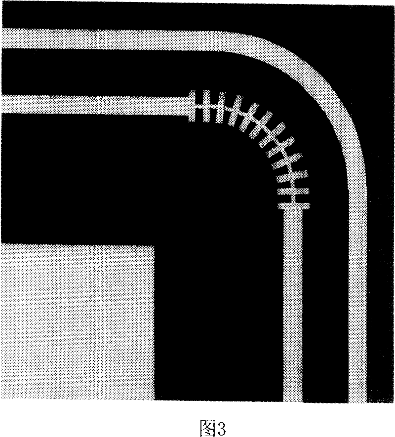
[0052] Embodiment 3: As shown in FIG. 3 , a deformed grid velocity compensation type 90° arc-shaped curved coplanar waveguide structure.
[0053] Since the structure is arc-shaped at the bend, the grid structure changes accordingly, forming a deformed grid.
[0054] Numerical calculation results
[0055] The 90° curved coplanar waveguides with grid structure types A1, C3, D2 and D3 are analyzed and calculated by simulation software, and some numerical calculation results are obtained. The specific structural settings are as follows: L=7.65mm; C3: S=4.7mm; D2: S=3.1mm; D3: S=4.925. Other structural parameters are shown in Table 1. Figure 8 and Figure 9 show the S of these four structures respectively 11 , S 21 The magnitude of the parameter varies with frequency. It can be seen from Figure 8 and Figure 9 that the reflection coefficient S 11 reduced, the transmission coefficient S 21 It increases in the higher frequency region, indicating that the transmission performance...
PUM
 Abstract
Description
Claims
Application Information
 - R&D
- Intellectual Property
- Life Sciences
- Materials
- Tech Scout
- Unparalleled Data Quality
- Higher Quality Content
- 60% Fewer Hallucinations
Browse by: Latest US Patents, China's latest patents, Technical Efficacy Thesaurus, Application Domain, Technology Topic, Popular Technical Reports.
© 2025 PatSnap. All rights reserved.Legal|Privacy policy|Modern Slavery Act Transparency Statement|Sitemap|About US| Contact US: help@patsnap.com


